PROTEUS XR/a
GE MEDICAL SYSTEMS Operator Manual
REV 11 DIRECTION 2259724-100
8-4
8-2-3 LAT Bar Angulation
Release the handle, then, turn the LAT bar to the position in which the keys on
the flange insert the slots on the spacer. Then, lock the handle.
THE LAT BAR IS NOT USED FOR HOLDING WHOLE PATIENT’S WEIGHT.
THE MAXIMUM FORCE ON THE LAT BAR SHALL NOT EXCEED 20 KG.
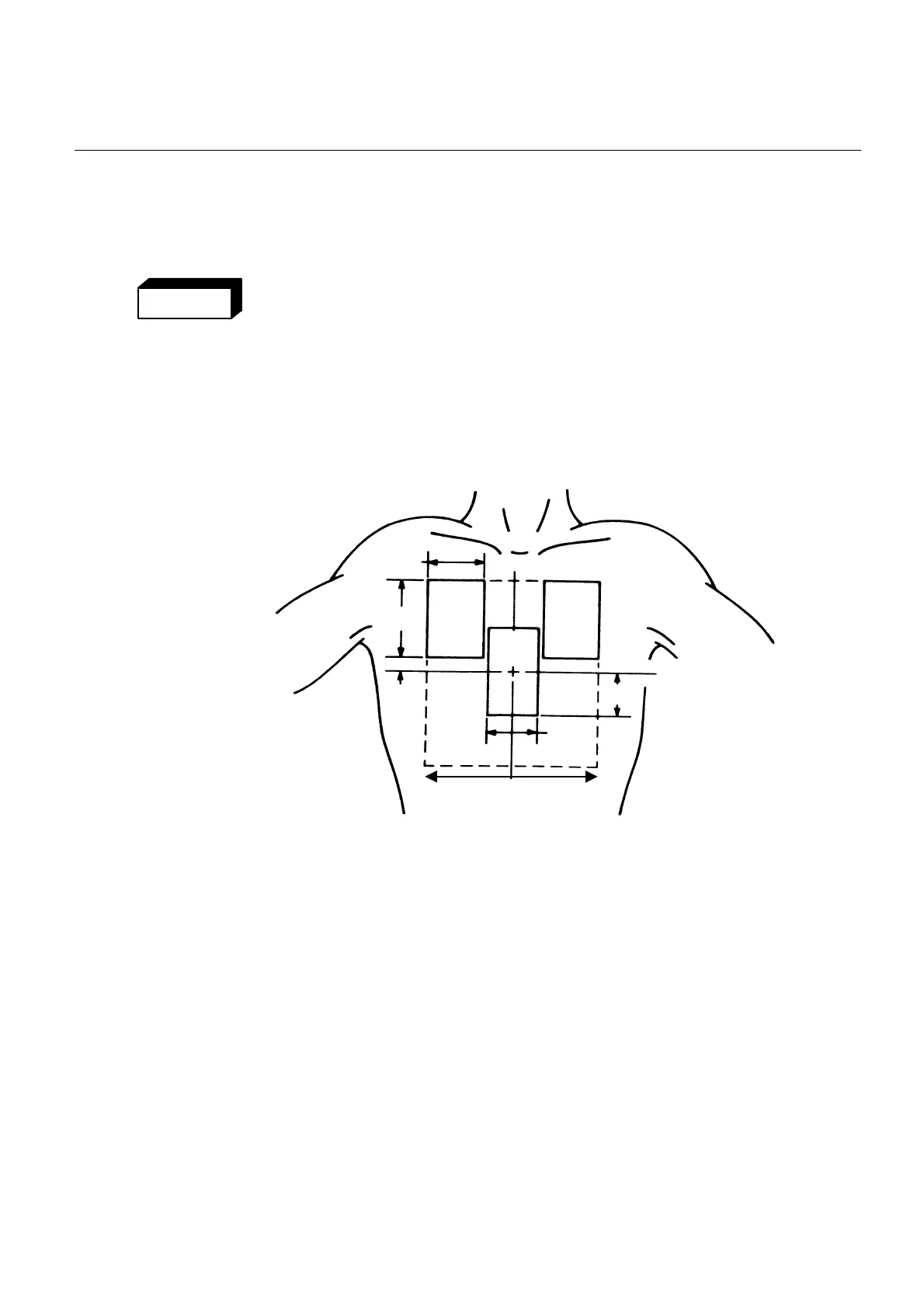
8-2-4 AEC Detector Areas-Optional Feature
The optional ion chamber in the wall stand contains three sensing areas. The
square areas in Illustration show the location of the three ion chamber areas.
ILLUSTRATION 8-3
POSITIONING OF ION CHAMBER DETECTORS
2
AREA
THE POSITION OF THE SENSING AREAS
AREA
(51mm)
(23mm)
3.6
(92mm)
2.2
(56mm)
2
(51mm)
X-RAY FIELD
CENTER LINE
X-RAY FIELD
CENTER LINE
13
AREA
205mm
8 in.
• Sensing area Number 2 is at the center of the x-ray beam.
• Area Number 1 and Area Number 3 can be selected to cover an exposure of
two symmetrical parts of the body at a time, such as the lungs or the kidneys.
• If this is the case, care should be taken to center the patient and detector
areas accordingly.
WARNING
FOR TRAINING PURPOSES ONLY!
NOTE: Once downloaded, this document is UNCONTROLLED, and therefore may not be the latest revision. Always confirm revision status against a validated source (ie CDL).

 Loading...