B-20 T60 Transformer Protection System GE Multilin
B.4 MEMORY MAPPING APPENDIX B
B
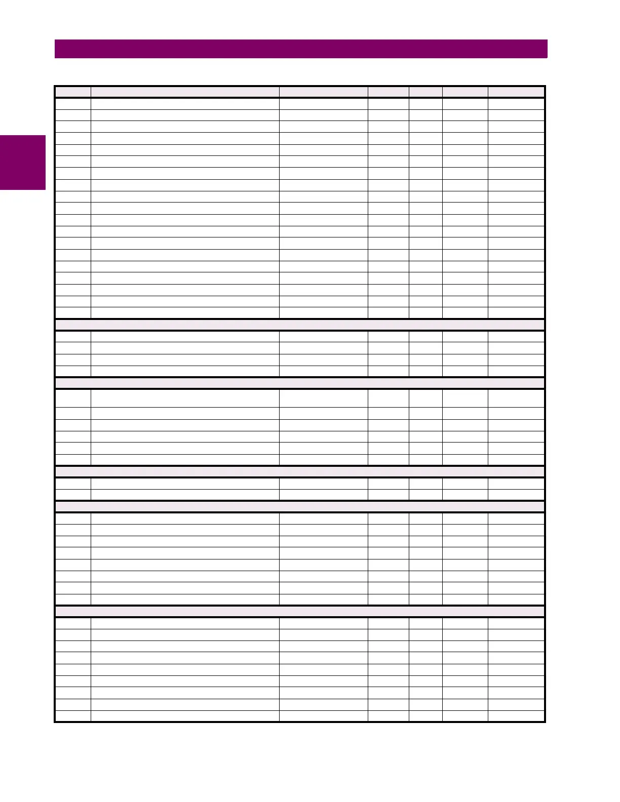
2306 Transformer Differential 2nd Harm Iad Angle -359.9 to 0 degrees 0.1 F002 0
2307 Transformer Differential 5th Harm Iad Magnitude 0 to 999.9 % fo 0.1 F001 0
2308 Transformer Differential 5th Harm Iad Angle -359.9 to 0 degrees 0.1 F002 0
2309 Transformer Differential Phasor Ibd Magnitude 0 to 30 pu 0.001 F001 0
230A Transformer Differential Phasor Ibd Angle -359.9 to 0 degrees 0.1 F002 0
230B Transformer Restraint Phasor Ibr Magnitude 0 to 30 pu 0.001 F001 0
230C Transformer Restraint Phasor Ibr Angle -359.9 to 0 degrees 0.1 F002 0
230D Transformer Differential 2nd Harm Ibd Magnitude 0 to 999.9 % fo 0.1 F001 0
230E Transformer Differential 2nd Harm Ibd Angle -359.9 to 0 degrees 0.1 F002 0
230F Transformer Differential 5th Harm Ibd Magnitude 0 to 999.9 % fo 0.1 F001 0
2310 Transformer Differential 5th Harm Ibd Angle -359.9 to 0 degrees 0.1 F002 0
2311 Transformer Differential Phasor Icd Magnitude 0 to 30 pu 0.001 F001 0
2312 Transformer Differential Phasor Icd Angle -359.9 to 0 degrees 0.1 F002 0
2313 Transformer Restraint Phasor Icr Magnitude 0 to 30 pu 0.001 F001 0
2314 Transformer Restraint Phasor Icr Angle -359.9 to 0 degrees 0.1 F002 0
2315 Transformer Differential 2nd Harm Icd Magnitude 0 to 999.9 % fo 0.1 F001 0
2316 Transformer Differential 2nd Harm Icd Angle -359.9 to 0 degrees 0.1 F002 0
2317 Transformer Differential 5th Harm Icd Magnitude 0 to 999.9 % fo 0.1 F001 0
2318 Transformer Differential 5th Harm Icd Angle -359.9 to 0 degrees 0.1 F002 0
Transformer Thermal Inputs Actuals (Read Only)
2330 Transformer Top Oil Temperature 0 to 300 °C 1 F002 0
2331 Transformer Hottest Spot Temperature 0 to 300 °C 1 F002 0
2332 Transformer Aging Factor 0 to 6553.5 PU 0.1 F001 0
2333 Transformer Daily Loss Of Life 0 to 500000 Hours 1 F060 0
Synchrocheck Actuals (Read Only) (4 Modules)
2400 Synchrocheck 1 Delta Voltage -1000000000000 to
1000000000000
V1F060 0
2402 Synchrocheck 1 Delta Frequency 0 to 655.35 Hz 0.01 F001 0
2403 Synchrocheck 1 Delta Phase 0 to 359.9 degrees 0.1 F001 0
2404 ...Repeated for Synchrocheck 2
2408 ...Repeated for Synchrocheck 3
240C ...Repeated for Synchrocheck 4
Field Unit Raw Data Settings (Read/Write Setting)
2460 Field Raw Data Port 0 to 7 --- 1 F244 6 (H1a)
2461 Field Raw Data Freeze 0 to 1 --- 1 F102 0 (Disabled)
Remote Double-Point Status Inputs (Read/Write Setting Registers) (5 Modules)
2540 Remote Double-point Status Input 1 Device 1 to 32 --- 1 F001 1
2541 Remote Double-point Status Input 1 Item 0 to 64 --- 1 F606 0 (None)
2542 Remote Double-point Status Input 1 Name 1 to 64 --- 1 F205 "RemDPS Ip 1"
2548 Remote Double-point Status Input 1 Events 0 to 1 --- 1 F102 0 (Disabled)
2549 ... Repeated for double-point status input 2
2552 ... Repeated for double-point status input 3
255B ... Repeated for double-point status input 4
2564 ... Repeated for double-point status input 5
Phasor Measurement Unit Actual Values (Read Only)
256D PMU 1 Phase A Voltage Magnitude 0 to 999999.999 V 0.001 F060 0
256F PMU Unit 1 Phase A Voltage Angle -180 to 180 ° 0.1 F002 0
2570 PMU 1 Phase B Voltage Magnitude 0 to 999999.999 V 0.001 F060 0
2572 PMU 1 Phase B Voltage Angle -180 to 180 ° 0.1 F002 0
2573 PMU 1 Phase C Voltage Magnitude 0 to 999999.999 V 0.001 F060 0
2575 PMU 1 Phase C Voltage Angle -180 to 180 ° 0.1 F002 0
2576 PMU 1 Auxiliary Voltage Magnitude 0 to 999999.999 V 0.001 F060 0
2578 PMU 1 Auxiliary Voltage Angle -180 to 180 ° 0.1 F002 0
2579 PMU 1 Positive Sequence Voltage Magnitude 0 to 999999.999 V 0.001 F060 0
Table B–10: MODBUS MEMORY MAP (Sheet 12 of 74)
ADDR REGISTER NAME RANGE UNITS STEP FORMAT DEFAULT