34
Figure 16 - 7-segment font
! “ # $ % & ‘ ( )
* + , - . / 0 1 2 3
4 5 6 7 8 9 : ; < =
> ? @ A B C D E F G
H I J K L M N O P Q
R S T U V W X Y Z [
3.1.2.2. Scrolling messages
The SV (650) and F (1250 and 1350) displays can show scrol-
ling alphameric messages. These messages, up to 32 cha-
racters in length, appear:
• during configuration, describing the active parameter;
• during functioning, after the tripping of alarms, digital in-
puts and logic function outputs, if the relative messages
were enabled
Message texts can be set via PC with GF_eXpress software.
There are 3 message groups, one for each of the 3 languages
provided, selectable from the HMI menu with the LANG.n
parameter. Each group contains up to 25 messages.
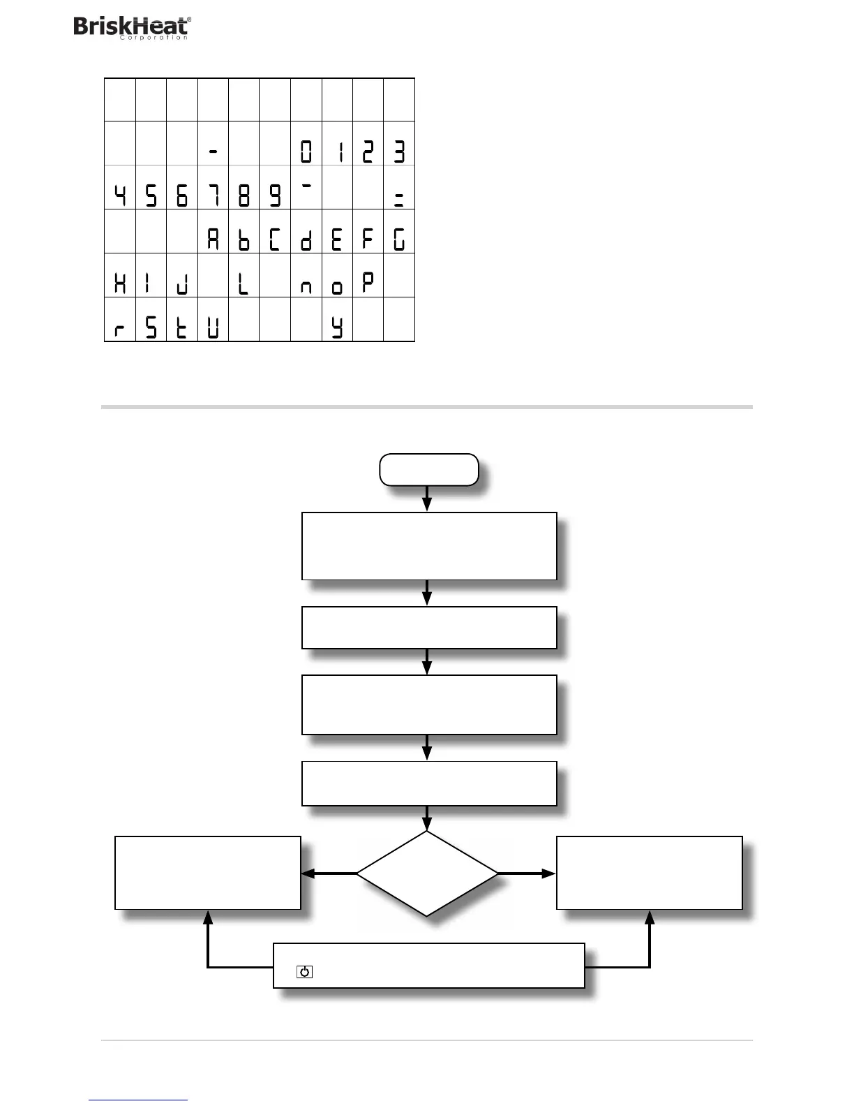
3.2. Sequence at power-on
The following diagram shows the controller sequence at power-on.
Note: the USB-TTL programming cable must be disconnected.
*) Any error is signaled by the message EEPROM CHECKSUM ERROR.
**) Only if MANUAL mode was used before the controller was powered off.
1. Program code self-diagnostics.
2. Configuration read by EEPROM.
3. Check of data consistency. *
4. Recognition of available options.
Initialization of input and
output devices based on configuration.
DISPLAY ON
All display segments are on.
3 flashes at interval of about 1 second
CONTROL ON
As per the set configuration.
** MANUAL
CONTROL
HOME
The displays show the process
variable and the % value of
power.
HOME
The displays show the process
variable, the setpoint or other
defined parameter.
AUTOMATIC/MANUAL switching via key
or digital input or serial communication.
Power On
3. COMMISSIONING
FalseTrue