819XX_MAN_GRM-H_11-2022_ENG_pag. 11
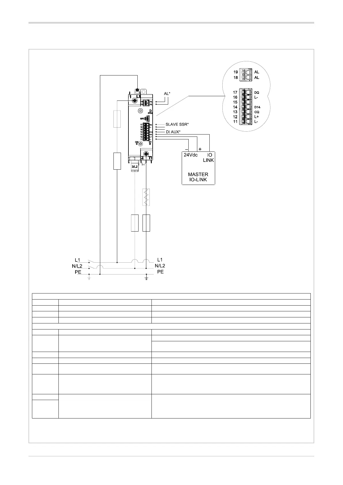
Load
Fuse
Fuse: fast fuse, see fuse table
Fuse gg: see fuse section
* Input/ output configurable functions
Connection for single phase load
Fuse
GG
Fuse
GG
Power terminals
Ref. Description Notes
1/L1 Line Connection
2/T1 Load Connection
3/L2 Line voltage reference connection
I version signal connector (IO-LINK)
11/L- Power GND
12/L+ + V DC power supply
GRM-H power supply (Range from 10 to 30 V DC, Imax = 20 mA at 24V)
GRM-H-90/120A-..FAN63: GRM-H + Fan power supply
(Range from 20 to 27 V DC, Imax <150 mA at 24V with Fan active)
13/CQ IO-LINK communication line
14/D14 Auxiliary digital input 1 Digital input: 5-30V, max 3mA
16/L-
GND alarm output
(common to terminal 11/L-)
17/DQ
Master-Slave output /Alarm output /
Digital input auxiliary 2
Master-Slave output: Output voltage: Us - 0.7Vdc, Iout max = 15mA
Alarm output: PNP output normally not active (Con gurable as normally active),
output voltage: Us – 0.7V DC , Iout max =15mA
Digital input: 5-30V, max 3mA
18/AL
Alarm output / Master-Slave output
Dry contact N.O.
Maximum current: 150mA
Maximum voltage = 30 Vdc / 25Vac
Closed contact impedance <1 Ω
Open contact impedance> 1 MΩ
19/AL
VERSION WITH IO-LINK INPUT
2.6.1. IO-Link control

 Loading...


