819XX_MAN_GRM-H_11-2022_ENG_pag. 78
6.3.3. Process data mapping
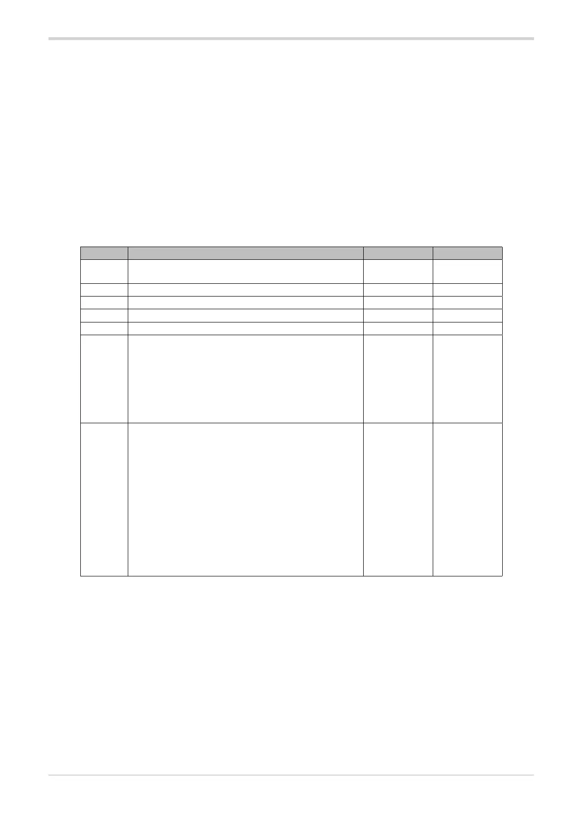
The device has the following Process Data Input mapping:
Word n Meaning Offset Length
6
Actual output power Ou.P (Percentage value of
delivered power))
96 16 bit
5 Load current Ld.A (RMS load current) 80 16 bit
4 Load voltage Ld.V (Load voltage) 64 16 bit
3 Load power Ld.P (Power on load) 48 16 bit
2 Load impedance Ld.I (Load impedance) 32 16 bit
1
STATUS2
Bit 6..15= Not used
Bit 5= STATUS2_NO_CURRENT
Bit 4= STATUS2_NO_VOLTAGE
Bit 3= STATUS2_SSR_SHORT
Bit 2=
(*)
Bit 1= STATUS2_HB
Bit 0= (*)
16
16 bit
0
STATUS3
Bit 15= Not used
Bit 14=STATUS3_DRYOUT
Bit 13=STATUS3_CURRENT_SENSOR_BROKEN
Bit 9...11= Not used
Bit 8=STATUS3_OVER_RMS_CURRENT
Bit 7=STATUS3_OVER_PEAK_CURRENT
Bit 6=STATUS3_SHORT_CIRCUIT_CURRENT
Bit 5=STATUS3_60HZ
Bit 4=STATUS3_FREQUENCY_WARNING
Bit 3=STATUS3_SOFTSTART_END
Bit 2=STATUS3_SOFTSTART_ACTIVE
Bit 1=STATUS3_SCR_OVER_HEAT
Bit 0=STATUS3_SCR_TEMP_SENSOR_BROKEN
0
16 bit
(*) Bits not published in the IODD file but still available.
Bit 0 OR of Bit 1, Bit 2
Bit 2 Power Fault (OR of Bit 3,4,5)
(**) Bits not published in the IODD file but still available.
Bit 2 Phase soft start on
Bit 3 Phase soft start end
Bit 5 50Hz (0) / 60Hz (1)
6.3.2. SIO mode and IO-Link mode
The static group supports both SIO mode and IO-Link
mode.
In SIO mode the static group behaves like an
actuator: the status of the HB alarm is available on
pin 13.
In IO-Link mode the static group communicates with
a standard IO-Link master on pin 13 of the push-in
connector.
Pins 14,17,18/19 str available as a configurable
auxiliary alarm outputs (see chapters Alarms and
Outputs) or as auxiliary input.
In SIO mode the device :
- maintains control of the load, continuing to provide
the last power set in IO-Link mode. To change the
required power, change mode, from SIO to IO-Link
mode.
- commands the pin 13/CQ to acts as an alarm unit,
transmitting the status of the alarms as set in the out1
parameter (replicates the alarm output status of pin9
/ DQ).

 Loading...


