819XX_MAN_GRM-H_11-2022_ENG_pag. 24
3.1.4. Key
NORMAL
OPERATION
LED: on or flashing as
indicated in the
LED chapter
LED status
with key
pressed
Key
pressed
Key pressed > 3 s
and then released
Key
repeatedly
pressed and
released
> 0.2 s
Key pressed > 9 s
and then released
Key pressed > 3 s
and then released
Key pressed > 15 s
and then released
Key
repeatedly
pressed and
released
> 0.2 s
Key pressed > 3 s
and then released
Key pressed > 3 s
and then released
Key
repeatedly
pressed and
released
> 0.2 s
Key
pressed
> 6 s
Key
pressed
> 12 s
3 s
3 s
SETTINGS TO MODIFY NUMBER
OF LOADS (HB.P) and
CALIBRATION HB
GREEN LED: on
SETTINGS TO MODIFY
ANALOGUE INPUT TYPE (TYP)
and CALIBRATION OF FULL
SCALE POTENTIOMETER
(for model GRM-H-x-x-AN-x-x-x-x-x-x-x only)
RED LED: on
SETTINGS TO MODIFY THE
NUMBER OF MINIMUM START
CYCLES (BF.CY)
(only if hd.5 = BF)
BLUE LED: on
NUMBER OF
LOADS INDICATION
GREEN LED: it flashes according
to the value of Hb.P
ANALOGUE INPUT TYPE
INDICATION
RED LED: flashes according
to the tyP value
MINIMUM NUMBER OF START
CYCLES INDICATION
BLUE LED: flashes according
to the value of bF.CY
NUMBER OF LOADS
CONFIRMATION
GREEN LED: quickly
flashes for 1s
NUMBER OF LOADS
DATA ENTRY
GREEN LED: turns on by
pressing the key and turns off
by releasing the key
ANALOGUE INPUT
TYPE DATA ENTRY
RED LED: turns on by
pressing the key and turns off
by releasing the key
ANALOGUE INPUT TYPE
CONFIRMATION
RED LED: quickly flashed
for 1s
GREEN LED RED LED BLUE LED
MINIMUM NUMBER
OF START CYCLES
CONFIRMATION
BLUE LED: quickly
flashes for 1s
MINIMUM NUMBER
OF START CYCLES
DATA ENTRY
BLUE LED: turns on by
pressing the key and turns off
by releasing the key
FULL SCALE
POTENTIOMETER
CALIBRATION ON
(**)(for tyP = 6 only)
HB
CALIBRATION ON
(*)
3 s
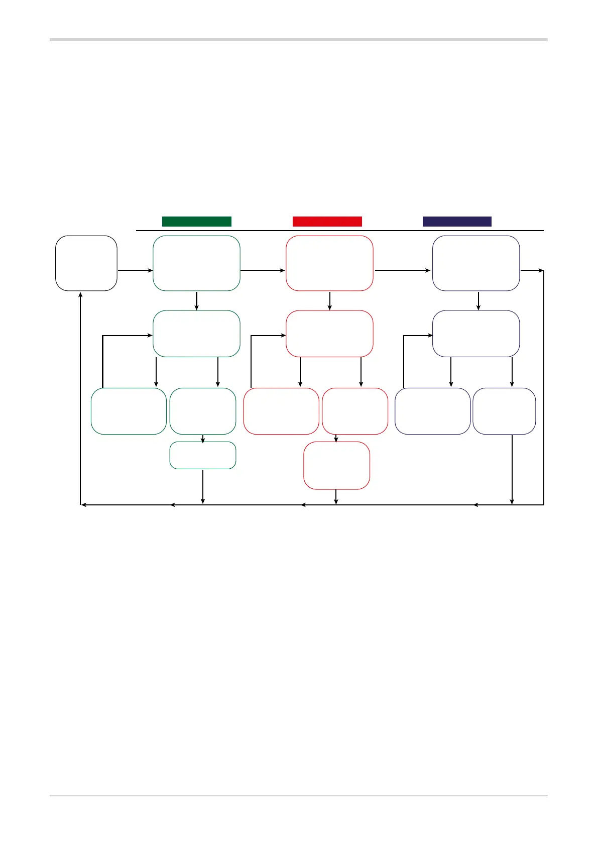
Some basic settings can be edited or the load current
calibration phase started using the key and the LEDs
on the front of the object. The basic settings are:
• “Partial HB alarm threshold learning” command See
chapter Allarme HB (Heater Break) ”5.2.1.1. HB
alarm threshold teach-in/calibration function” a
pagina 35 on the Manual (for GRM-H-x-x-x-x-1-x-x-
x-x-x models)
• Number of loads in parallel under a single zone
for calculating the partial HB alarm threshold (see
parameter Hb.P)
• Type of analogue input (see tyP parameter) (for GRM-
xxx-AN-xxxxxx models)
•
Minimum number of cycles of the Burst Firing mode
(see parameter bF.Cy) (only if hd.5 = BF).
• Full scale potentiometer calibration
• Alarm memory reset
• Alarm reset SHORT_CIRCUIT_CURRENT
Below are the instructions to change settings via key and
feedback from the front LED.
With the key released for at least 30 s (15 s if you are in the
phase of indicating the setting to be modified) you return to
normal operation.
* After activating the HB calibration, the device automatically
activates the power output ONLY in the case of HSC / PA
firing with PS.E = 3 (Softstart for IR lamps). In all other
conditions the device waits for the command signal (digital
ON, analog or IO-Link signal is recommended > 50%).
A few operating waves are enough for the device to register
the current and voltage value as the nominal value of the
load and exit calibration.
It is recommended to carry out calibration in load regime
conditions. This is to avoid false alarms due to current drop,
not due to load break in parallel, but to the consumption
of different current between resistors at room temp. and
working temp. Normal operations resume with the key
released for at least 15s.
** Custom calibration of the potentiometer is useful if the
potentiometer used does not reach the end of its stroke or
you don't want to use it to the end of its stroke. The device
will save the value read by the analog input in real-time and
will save it as upper full scale with Custom calibration.
Example, if you want to manage the potentiometer input
with a signal ranging from 0 to 4.5V (and not up to 5V),
position the potentiometer so that it generates 4.5V.
The 4.5V value will be saved as the upper limit.
At 0V, the power delivered will be 0.0%, at 4.5V 100.0%.

 Loading...


