14
80960G_MHW_GTF_05-2019_ENG
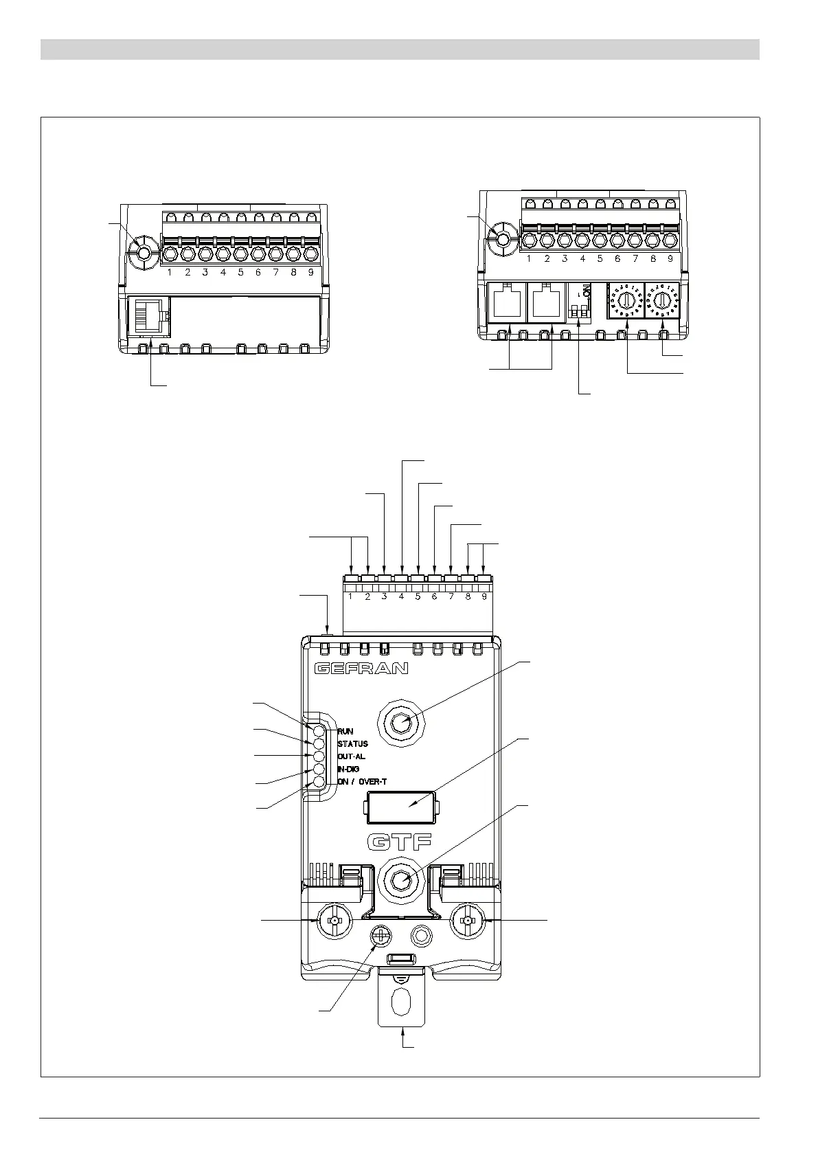
3.2 connections inPut/outPut Gtf 25-120a
Figure 11
Top view
WITHOUT option Fieldbus
Top view
WITH option Fieldbus
Key HB
J2
TTL port for
PC conguration
Key HB
J3, J4
RJ10 connectors
RS485 serial line
Modbus
Switch for serial line
Address x 10
Address x 1
Syncronous output for
Master/Slave connection
Alarm output
(solid state relay - HB option)
Key HB
Green Led (RUN)
Yellow Led (STATUS)
Red Led (Alarm output HB)
Yellow Led (Status digital input)
Led: Green = Thyristor ON
Yellow = Temperature OVER
1/L1
LINE connection
3/L2
Reference connection
of line voltage
PE
EARTH
2/T1
LOAD connection
Fixing screw
at heatsink
Identication label
Fixing screw
at heatsink
J1
Power supply /control
connector
Power supply terminal 24Vac/Vdc
Digital input (PWM input)
Potentiometer output power supply (+5Vdc)
Input control signal (+)
(GND)

 Loading...


