16
80960G_MHW_GTF_05-2019_ENG
3.4 functions of inDicator leDs
Description of LEDs
Table 7
LED DESCRIPTION COLOR
RUN
Flashing during normal operation
green
On steadily: according to FW setting (see SW manual)
STATUS
Off : during normal operation
yellow
On : according to FW setting (see SW manual)
ALARM State HB alarm output / Power Fault Alarm / Fuse Open red
DI State digital input yellow
ON / OVER-TEMP
.Green: thyristor on control state green
Yellow: ON Thyristor overtemperature alarm yellow
The state of the LEDs matches the corresponding parameter, except in the following special cases:
- LED 1 (green) + LED 2 (yellow) both ashing rapidly: autobaud in progress
- LED 2 (yellow) ashing rapidly: SSR temperature sensor broken or SSR Over Heat or Rotation Error or Fuse_open
(GTF 150...250A) or Short_Circuit_Current or Line-Load Terminals Over Heat (GTF 150...250A)
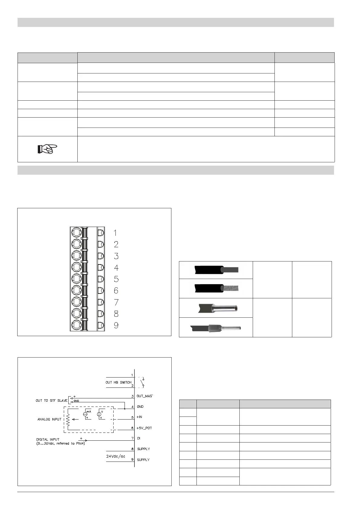
3.5 control connector
3.5.1 Connector J1 GTF 25-120A
Figure 13
CONNECTOR J1 GTF 25-120A
(CONTROL)
Table 8
0,2 - 2,5mm
2
24-14AWG
0,25 - 2,5mm
2
23-14AWG
Figure 14
Connection schema J1 GTF for 25-120A
CONNECTOR J1 GTF 25-120A
Table 9
PIN NAME DESCRIPTION
1
OUT AL HB OUT Alarm Switch (HB)
2
3 OUT_Master Control output Slave (+7V)
4 GND GND Control analog input
5 + IN + Control analog input
6 +5V_POT Output alim. potentiometer
7 IN_DIG Digital input & PWM Input
8 24V Supply
Supply 18...32 Vac/Vdc
9 24V Supply

 Loading...


