34
80960G_MHW_GTF_05-2019_ENG
4 • INSTALLATION OF THE SERIAL PORT
A network typically has a Master that “manages” communication by means of “commands,” and Slaves that carry out these
commands.
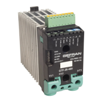
GTF modules are considered Slaves to the network master, which is usually a supervision terminal or a PLC.
It is positively identified by means of a node address (ID) set on rotary switches (tens + units).
A maximum of 99 GTF, modules can be installed in a serial network, with node address selectable from “01” to “99”
GTF modules have a ModBus serial (Optional)
The MODBUS RTU port 1 has the following factory settings (default):
Parameter Default Range
ID
1
1...99
BaudRate 19,2Kbit/s 1200...19200bit/s
Parity None Odd/Even/None
StopBits
1 -
DataBits
8 -
The following procedures are indispensable for the Modbus protocol.
Set the rotary switch at “0+0” for AutoBaud function
Parameter
Position
rotary switches
tens unit
AutoBaud 0 0
Allows setting of thecorrect BaudRate value automatically detecting the master
transmission frequency.
PLC / HMI GTF with RS485
RS485 MODBUS RJ10 Cable
------------------------------------------>
NOTE
The standard products DO NOT feature the comunication RS485 Modbus serial port, but can be configured via PC with Gefran
GF-Express Software, by connecting it to TTL port of GTF to PC, by means of TTL cable equipped with SW.
PC
Gefran Adapter
F049095
F043956 or
GTF Standard
RS232 or USB TTL cable RJ10
---------------> --------------->
NEVER connect TTL adaptator to RS485 serial port of GTF.
NEVER connect TTL connector or GTF to a RS485 serial web .
Danger of product damage!!
 Loading...


