28
80960G_MHW_GTF_05-2019_ENG
NOTES: USE WITH INDUCTIVE LOADS AND TRANSFORMERS
a
Connect a varistor (MOV) between each wire of the primary transformer and ground.
Varistor data: rated voltage 660Vrms,…, 1000Vrms; minimum energy 100J
b The maximum current controllable by the device is less than the product’s rated value (see technical data).
c In ZC and BF trigger mode, use the Delay-triggering function to limit peak magnetization current.
d In PA trigger mode, use the Softstart function.
e DO NOT use HSC trigger mode.
f DO NOT connect RC snubbers in parallel to the transformer primary.
g Select the inductive load using the Hd.1 parameter (ref. Software manual)
Trigger modes
The GTF has the following power control modes:
- modulation via variation of number of conduction cycles with zero crossing trigger.
- modulation via variation of phase angle
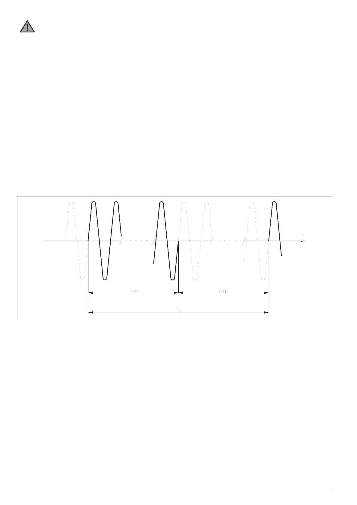
Zero Crossing mode
This function eliminates EMC noise. This mode controls power on the load via a series of conduction ON and non
conduction OFF cycles
ZC constant cycle time (Tc ≥ 1 sec, settable from 1 to 200 sec) Cycle time is divided into a series of conduction and non
conduction cycles in proportion to the power value to be transferred to the load.
Figure 39
For example, if Tc = 10sec, if the power value is 20% there is conduction for 2 sec (100 conduction cycles @ 50Hz)
and non conduction for 8 sec (400 non conduction cycles @ 50Hz).

 Loading...


