Group 12: Monitoring Parameters
Code Parameter Name Setting Range Default Unit
Control mode
Attribute
V/f
V/f
+PG
SLV SV
PM
SV
PM
SLV
SLV2
1: Output Current
2: Output Voltage
3: DC voltage
4: Temperature
5: PID feedback
6: Analog Signal Input. (AVI)
7: Analog Signal Input. (ACI)
12-01
PID Feedback Display Mode
(LED)
0: Display the Feedback Value by Integer
(xxx)
0 O O O O O O O *6
1: Display the Feedback Value by the
Value with One Decimal Place (xx.x)
2: Display the Feedback Value by the
Value with Two Decimal Places (x.xx)
12-02
PID Feedback Display Unit
Setting (LED)
0: xxxxx (no unit) 0 O O O O O O O *6
1: xxxPb (pressure)
2: xxxFL (flow)
12-03 Line Speed Display (LED) 0~60000
1500/
1800
rpm O O O O O O O *6
12-04
Modes of Line Speed
Display (LED)
0: Display Inverter Output Frequency 0 - O O O O O O O
*1
*6
1: Display Line Speed with integer (xxxxx)
2: Display Line Speed with the First
Decimal Place (xxxx.x)
3: Display Line Speed with the Second
Decimal Place (xxx.xx)
4: Display Line Speed with the Third
Decimal Place (xx.xxx)
12-05
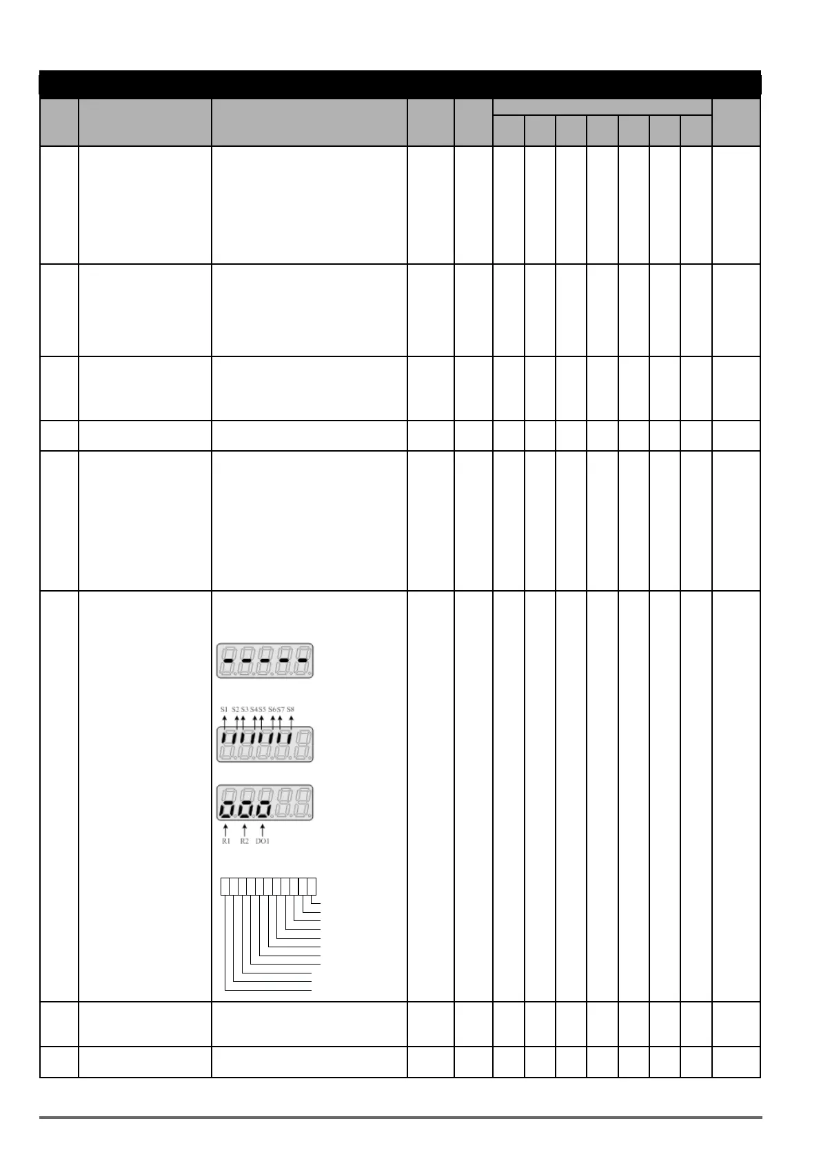
Status Display of Digital
Input & Output Terminal
LED display is shown as below: - O O O O O O O
(LED / LCD) no input
correspondences to input and output
LCD display is shown as below
00 00 00 0 0
Input Terminal(S8)
Input Terminal(S7)
Input Terminal(S6)
Input Terminal(S5)
Input Terminal(S4)
Input Terminal(S3)
Input Terminal(S2)
Input Terminal(S1)
0:OPEN
1:CLOSE
000
Output Terminal(DO1)
Output Terminal(R2)
12-06
~
12-10
Reserved
12-11
Output Current of Current
Fault
Display the output current of current fault - A O O O O O O O
50 VDI100 • Start-up and Installation Manual

 Loading...
