38
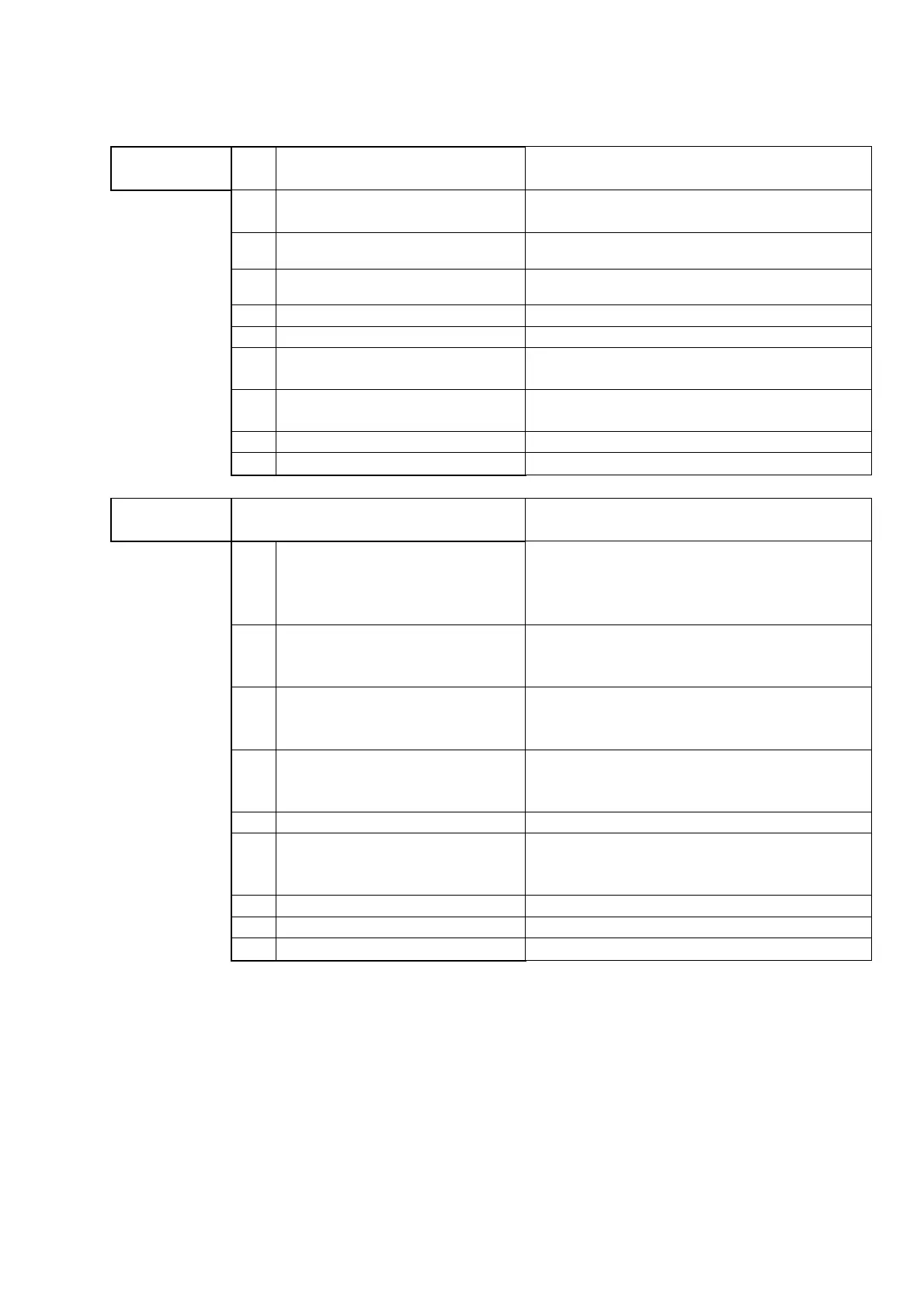
Übersicht Anschlussmöglichkeiten / Overview connection scheme:
#Interface
Pin
Nr..
Control
SUB-D 9 pole female Description
1
Reverse [Dig. Input 3,3V to 5V;
High Pegel]
Signal high active, reverse the motordirection;
limited 25Seconds!
2 RS485 B
RS485 Communicaton line to Interface and
Akku
3 RS485 A
RS485 Communicaton line to Interface and
Akku
4 Analog Setpoint [2,5V@100%] Analog Setpoint for motor pwm or speed loop
5 GND [Signal] GND for analog and digital inputs
6
Enable [Dig. Input 3,3V to 5V];
function to parameterize Signal high active, enabling the mc
7
PF3 [Dig. Input 3,3V to 5V];
function to parameterize
Signal high active, RS485 remote setpoint active
and other functions
8 Beeper [Open Collector 100mA] Signal for warning - mc enabled
9 +5V/max. 400mA 5V Supply for Analog and digital functions
# AUX
Pin
Nr..
MC-AUX
SUB-D 9 pole male Description
1
LED+ (60V/0,25A Profet); function
to parameterize
switched protected battery voltage; function
parameterizable through: P_141
funktion_out_porte5; functions see parameter
documentation
2
PF3 [Dig. Input 3,3V to 5V];
function to parameterize
Signal high active,function parameterizable
through: P_142 Reaktion_Pin_F3; functions see
parameter documentation
3
PF4 [Dig. Input 3,3V to 5V];
function to parameterize
Signal high active,function parameterizable
through: P_143 Reaktion_Pin_F4; functions see
parameter documentation
4
Port_R0_Out1 [Dig. Output OC
3,3V to 5V, max. 100mA]; function
to parameterize
Open Collector output, function parameterizable
through: P_145 out_portr0; functions see
parameter documentation
5 GND [Signal] GND for analog and digital inputs
6
DAC/AI [Analog. In/Output 2,5V
@100%]; function to
parameterize
Analog IN/OUT, function parameterizable
through: P_152 dacb_config; functions see
parameter documentation
7 TxD_232 / 5V TTL TxD RS232 communication line from MC
8 RxD_232 / 5V TTL RxD RS232 communication line to MC
9 +5V/max. 200mA 5V Supply for Analog and digital functions