554
26 / 44
6 Technical data
Control medium
Inert gases
Max. perm. temperature of control medium: 60 °C
Ambient conditions
Max. ambient temperature 60 °C
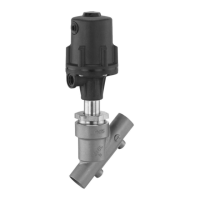
Technical data / Actuator
Actuator size Filling volume Piston diameter
B 0.01 dm³ 30 mm
0, 0K, 3, 3L 0.05 dm³ 50 mm
1, 1K, 4, 4L 0.125 dm³ 70 mm
2, 2K 0.625 dm³ 120 mm
Control pressure [bar]
Normally closed (NC)
Actuator size
B 4 - 8
0, 0K 4.8 - 7.0
1, 1K 5.5 - 7.0
2
2K
4 - 7 (DN 20 - 40) / 5 - 7 (DN 50 - 80)
4 - 7 (DN 40 + 50) / 5 - 7 (DN 65)
3, 3L, 4, 4L
min. control pressure see diagram /
max. control pressure 7 bar
Normally open (NO) / Double acting (DA)
0, 0K, 1, 1K, 2, 2K
max. 7 bar
(for values see diagram)
Working medium
Corrosive, inert, gaseous and liquid media which have no
negative impact on the physical and chemical properties of
the body and seal materials.
Max. perm. pressure of working medium see table
Medium temperature
Actuator B, Seat seal NBR Code 2 -10 to 80 °C
Actuator B, Seat seal PFA Code 30 -10 to 160 °C
Actuator 0, 1, 2, 3, 4 -10 to 180 °C
Actuator 0K, 1K, 2K, 3L, 4L -10 to 180 °C
Max. permissible viscosity 600 mm²/s (cSt)
Other versions for higher viscosities on request
Versions 0K, 1K, 2K, 3L and 4L are only valid for connection code 80 in combination with
valve body material C2 (only DN 15, 20, 25, 40, 50 and 65 / actuator B not available).
Max. operating pressure [bar]
Actuator
size
DN 6 DN 8 DN 10 DN 15 DN 20 DN 25 DN 32 DN 40 DN 50 DN 65 DN 80
Normally closed (NC) / Flow direction: under the seat
B 10101010 - - - - - - -
0 --121262.5-----
0K - - - 12 12 6 - - - - -
1 - - 25252010 74.53 - -
1K - - - 25 25 20 - 7 4.5 3 -
2 - - - - 2525201210 7 5
2K-----25-201210-
Normally closed (NC) / Flow direction: over the seat
3 - - 10 10 10 10 8.0 6.0 4.0 - -
3L - - - 10 10 10 - - - - -
4 - - 10101010101010 -
-
4L - - - 10 10 10 - 10 10 10
-
Normally open (NO) / Double acting (DA) / Flow direction: under the seat
0 --25252012-----
0K - - - 25 25 20 - - - - -
1 - - 252525252012 8 - -
1K - - - - - 25 - 20 12 8.0 -
2 ----25252525251810
2K-------251616-
For max. operating pressures the pressure / temperature correlation must be observed (see table on page 24).
All pressures are gauge pressures.
Maximum permissible seat leakage rate
Seat seal Standard Test procedure Leakage rate Test medium
PTFE, PFA, NBR DIN EN 12266-1 P12 A air