554
32 / 44
11 Installation and connection
Prior to installation:
G Ensure that valve body and seal material
are appropriate and compatible to handle
the working medium.
See chapter 6 "Technical data".
11.1 Installing the valve
WARNING
The equipment is subject to pressure!
® Risk of severe injury or death!
G Only work on depressurized plant.
WARNING
Corrosive chemicals!
® Risk of caustic burns!
G Wear appropriate protective
gear when installing.
CAUTION
Hot plant components!
® Risk of burns!
G Only work on plant that has
cooled down.
CAUTION
Never use the valve as a step or an aid
for climbing!
® This entails the risk of slipping-off or
damaging the valve.
CAUTION
Do not exceed the maximum
permissible pressure!
® Take precautionary measures to
avoid possible pressure surges
(water hammer).
G Installation work must only be performed
by trained personnel.
G Use appropriate protective gear as
specifi ed in plant operator's guidelines.
Installation location:
CAUTION
G Do not apply external force to the valve.
G Choose the installation location so that
the valve cannot be used as a foothold
(climbing aid).
G Lay the pipeline so that the valve body
is protected against transverse and
bending forces, and also vibrations and
tension.
G Only mount the valve between
matching aligned pipes.
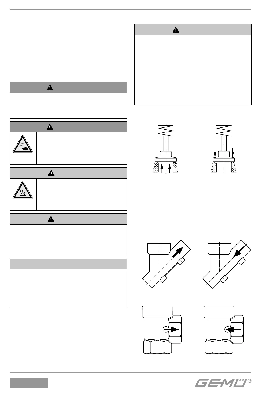
Direction of the working medium:
Flow direction:
under the seat* over the seat
Actuators B, 0, Actuators 3, 3L
0K, 1, 1K, 2, 2K 4, 4L
* Preferred fl ow direction with
incompressible liquid media to avoid
"water hammer"
The fl ow direction is indicated by an arrow
on the valve body:
2/2-way body 2/2-way body
Actuators B, 0, 0K, 1, 1K, 2, 2K Actuators 3, 3L, 4, 4L
Angle body Angle body
Actuators B, 0, 0K, 1, 1K, 2, 2K Actuators 3, 3L, 4, 4L