35 / 44
554
12.2 Replacement of seals
Replacement of seat seal: not for
actuator size B.
Important:
Replace gasket 4 during every
actuator disassembly / assembly.
1. Disassemble actuator A as described in
chapter 12.1, points 1-4.
2. Remove gasket 4.
3. Loosen nut d on spindle b (hold spindle b
with appropriate tool that will not damage
the spindle surfaces). Remove washer e
and seat seal 14.
4. Clean all parts, do not scratch or damage
the parts during cleaning.
5. Insert new seat seal 14.
6. Insert washer e.
7. Apply appropriate mounting glue on the
thread of spindle b.
8. Fix with nut d (hold spindle b with
appropriate tool that will not damage the
spindle surfaces).
9. Insert new gasket 4 in valve body 1.
10. Assemble actuator A as described in
chapter 12.3, points 1-5.
12.3 Assembly of actuator
CAUTION
Correct combination of actuator and
valve body!
® Risk of damage to the actuator and
valve body.
G Ensure correct combination of actuator
and valve body of control valves with a
reduced valve seat.
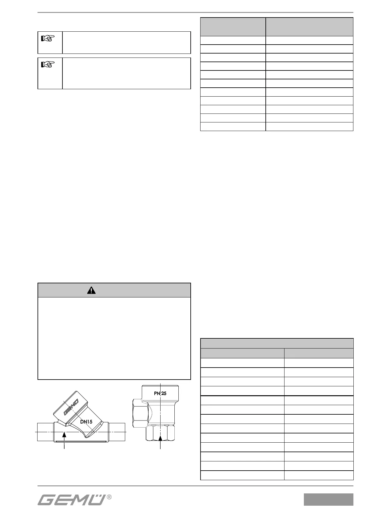
G Compare the product label of the
actuator with the valve body marking.
Rxxxx
Rxxxx
Valve body marking
2/2-way body
Valve body marking
Angle body
Product label of
actuator
Valve body marking
RAxxx R002
RBxxx R004
RCxxx R006
RDxxx R008
RExxx R010
RFxxx R012
RGxxx R015
RHxxx R020
RJxxx R025
RKxxx R032
RMxxx R040
1. Move actuator A to the open position.
2. Actuator rotatable 360°. Position of the
control medium connectors is optional.
3. Lubricate thread of the union nut a with a
suitable lubricant.
4. Actuator sizes 0, 0K, 1, 1K, 2, 2K, 3, 3L, 4,
4L: Place actuator A on valve body 1
approx. 90° anticlockwise to the desired
end position of the control medium
connectors and screw it down hand tight
using union nut a.
5. Actuator size B: place actuator A on valve
body 1 and tighten with a pin wrench
(pin size 3 mm). The control medium
connector is rotatable 360°, even after
the actuator is fi xed.
Actuator sizes 0, 0K, 1, 1K, 2, 2K, 3, 3L,
4, 4L: Tightening the union nut a with
an open-end wrench (torques see table
below) rotates the actuator clockwise
approx. 90° to the desired position.
6. Move actuator A to the closed position,
check function and tightness of
completely assembled valve.
Actuators B, 0, 1, 2, 3 and 4
Nominal size Torques [Nm]
DN 6 35
DN 8 35
DN 10 35
DN 15 35
DN 10 90
DN 15 90
DN 20 100
DN 25 120
DN 32 120
DN 40 150
DN 50 200
DN 65 260
DN 80 280