Foundations & Mounting
12 Installation Guidelines for Spark-Ignited Stationary Emergency Generators
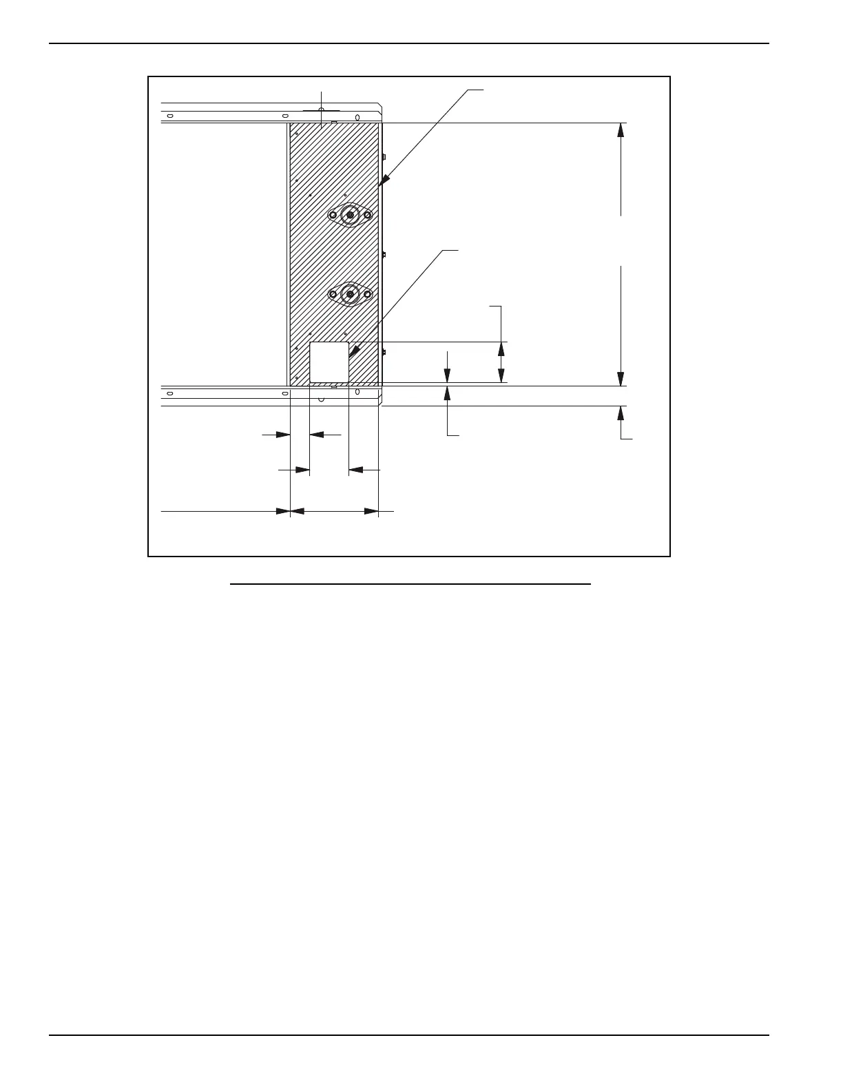
Figure 3-1. Typical Installation Drawing Stub Up Detail
3.2 — Mounting
3.2.1— Fixed Foundation
Use mounting holes in the base frame to fasten the unit to the foundation. Always use hardware of a suitable grade,
size and style.
3.2.2— Connections
All electrical connections must have flexible sections where they connect to the unit to isolate vibration. Properly sup-
port and secure all piping before installing the flexible connection.
3.2.3— Combustible Floor and Roof Protection
If the generator set must be installed on any combustible floor or roof, comply with the following rules:
• Place a layer of non-combustible insulation, followed by a layer of sheet metal, beneath the unit's mounting base
rails.
• Both the layer of insulation and the sheet metal must extend beyond the engine-generator base, to a distance of
at least six (6) inches (15.25cm) on all sides. See Figure 3-2.
For rooftop or building structure mounting, it is recommended that spring isolators be installed between the engine
frame and the mounting system. A minimum of 6 isolators are required and must be located at the front and rear cross
members and center of the frame.
000382
226 (8.9)
STUB-UP AREA
100
(3.9)
50
(1.9)
51
(2.0)
9
(.4)
104.5
(4.1)
674
(26.5)
STUB-UP
AREA
CIRCUIT BREAKER
NEUTRAL AND CUSTOMER
CONNECTION OPENING
HIGH AND LOW
VOLTAGE
STUB-UP AREA
DIMENSIONS: MM [INCH]
 Loading...