Gaseous Fuel Systems
Installation Guidelines for Spark-Ignited Stationary Emergency Generators 27
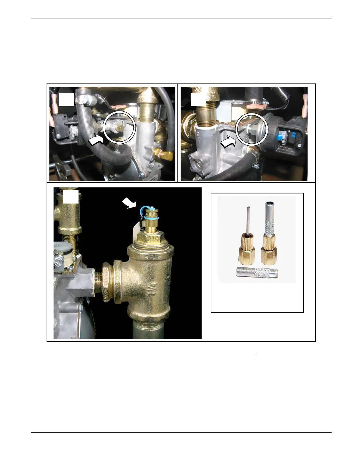
NOTE: Below 45º F. the neoprene core of the plug does not recover it's original shape as rapidly as it would at
higher temperatures. Therefore, upon removal of the gauge adapter probe, the valves may not close fully and
immediately, or they may remain slightly open until the operating temperature is above 45º F. Lower pressures
and the length of time the gauge adapter probe is inserted also can affect the valve closing rate. The protective
cap is provided to eliminate the small amount of leakage that might occur following removal of the gauge
adapter probe.
8. Tighten protective cap to prevent tampering.
Figure 5-4. Fuel Pressure Test Points
5.6.2— Final Test Procedure
The following test must be performed at startup to document and validate fuel system operation. It requires a load bank
connected to the unit, or a combination of load bank and system load, to bring the unit to its full rated kW load capacity.
Measure the fuel supply pressure under each of the following conditions:
1. Static Pressure. Pressure when the unit is not running. Must not exceed the maximum pressure listed in the unit
specification sheet.
A B
C
Gauge Adapter
1/8 Inch Diameter Probe
Part No. 0K2341