Electrical System
32 Installation Guidelines for Spark-Ignited Stationary Emergency Generators
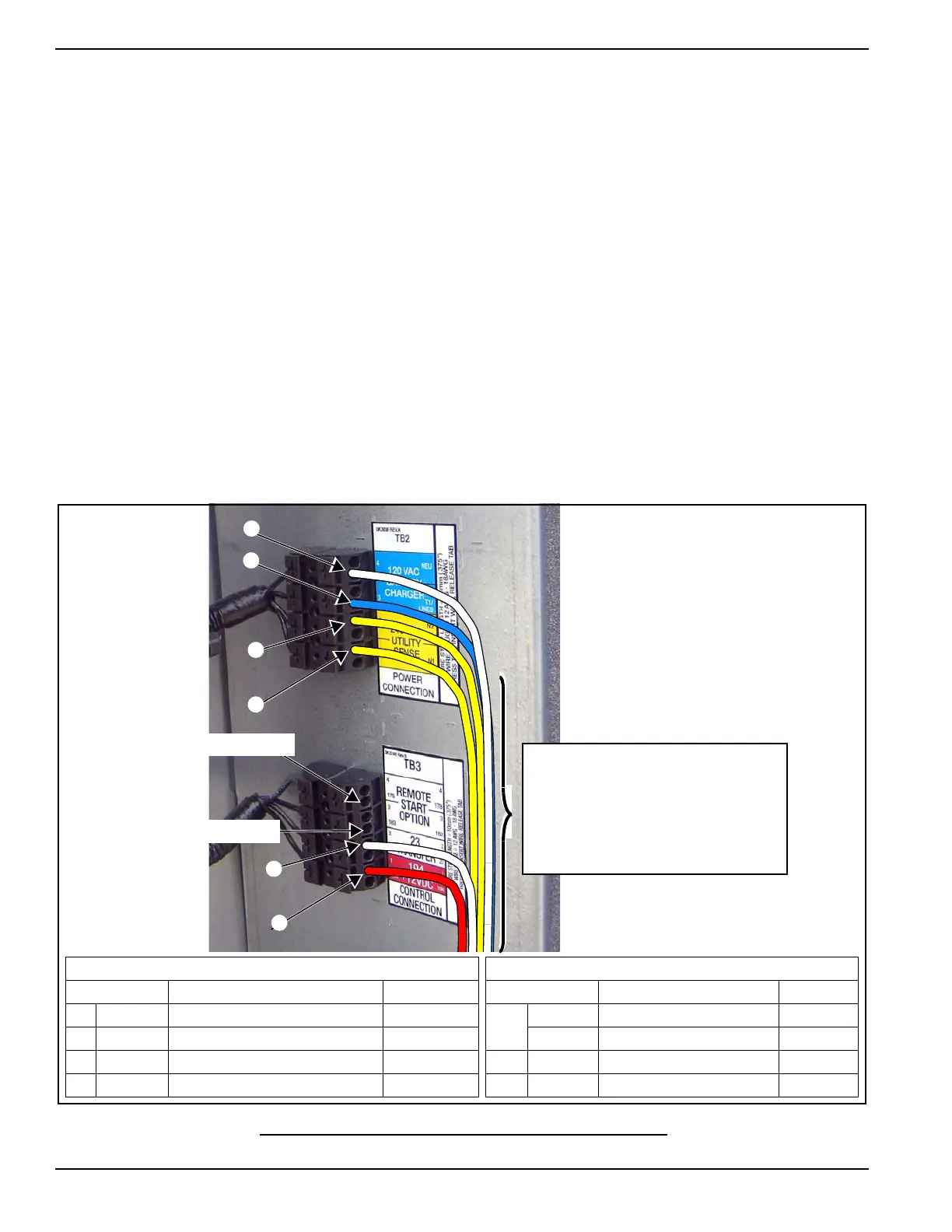
6.6 — Control Wiring Connections
The Control Wire Customer Connection block is where all of the control wiring is connected. Depending on the type of
system, this wiring includes the following:
6.6.1— RTS Series Transfer Switch With T1 Fuse/Connection
NOTE: The control wire customer connections typically use Class 1 Wiring Methods (verify with AHJ). Always follow
the standards and methods appropriate to the circuits being wired.
NOTE: T1 is the 120 VAC power supply for the control panel battery charger. This circuit must be powered whether the
transfer switch is in utility or generator mode. If the circuit loses power the control board will generate a warning (Bat-
tery Charge AC Fail).
NOTE: Observe the maximum wire size for the terminal strip connections shown in the unit wiring diagram.
For battery charging, connect neutral in TB2 to neutral in the transfer switch. See NOTE below for transfer switches
without T1.
Connect T1 in TB2 to T1 in the transfer switch. This is 120 volt supply to the unit's battery charger (normal RTS
transfer switch).
Connect N1, N2 sensing wires in TB2 to N1 and N2 in the transfer switch. These two wires are utility sensing
wires.
Connect 23 in TB3 to 23 in the transfer switch. Connect 194 in TB3 to 194 in the transfer switch. These are the
transfer switch control wires.
Figure 6-4. Typical Control Wiring Connections
Control Wiring
Connections
NOTE: Wire colors are shown for
illustration purposes only.
TB3 Terminal Block
Terminal Function Voltages
178 Two Wire Start Control [GTS] 5-12 VDC
183 Two Wire Start Control [GTS] 5-12 VDC
23 Transfer Relay Control Wire 12-0 VDC
194 Power for Transfer Relay 12 VDC
TB2 Terminal Block
Terminal Function Voltages
Neutral Neutral for T1 Battery Charger Neutral
T1 Power for T1 Battery Charger 120 VAC
N2 Utility Sensing from Transfer Switch 208-277 VAC
N1 Utility Sensing from Transfer Switch 208-277 VAC
IMPORTANT: Control wiring must be
installed in the provided 600V rated
electrical sleeving. The sleeving is
shipped loose and can be found in
the manual bag attached to one of
the louvered panels of the enclosure.
NOTE: All wiring must comply
with NEC, state and local AHJ
requirements.
Two-Wire Start Option
Two-Wire Start Option
 Loading...