Electrical System
Installation Guidelines for Spark-Ignited Stationary Emergency Generators 31
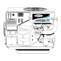
Figure 6-3. Typical High Voltage Connections
Customer load wiring consists of single-phase or three-phase connections between the generator Main Line Circuit
Breaker (MLCB) and the transfer switch. The wiring connects to lugs E1, E2, E3 (if three phase on MLCB), neutral, and
equipment ground at the generator and runs to the corresponding lugs in the transfer switch. All load wires, neutral and
ground should be marked and terminated in the correct lugs in the transfer switch. Ensure all wiring is properly
mounted and terminated at the appropriate connection points in both the generator and transfer switch. For general
information regarding wire type, temperature rating, size range, and wire lug torque specifications, see Tables 6-1 and
6-2. Always refer to NEC tables for specific requirements.
NOTE: For three phase applications, use phase rotation meter to verify that the generator phase rotation matches the
rotation of the utility.
NOTE: For three phase, delta configured alternators (voltage code J) the second leg (N2) must be bonded to all sec-
ond legs in the entire system.
Load Wiring
NOTE: Single
Connections
phase shown.
NOTE: See Figure
6-4 for typical
control wiring
connections.
E1
E2
Neutral
Ground
Knock Out Plug (Cold Weather Kit)
 Loading...