Electrical System
34 Installation Guidelines for Spark-Ignited Stationary Emergency Generators
NOTE: The following table is provided for references purposes only. Refer to the latest NEC, state and local
AHJ requirements for proper sizing.
6.7 — Optional Accessory Power
• Accessory power for optional items (battery warmer and block heater) should come from a customer utility supply
source (with appropriate sized breaker), which is also powered by emergency power during an outage.
• Optional user installed GFCI receptacles. Provides a place to plug in optional battery warmer and block heater.
NOTE: Remove knock out plug and route accessory wiring to customer supplied weather-proof junction box. See Fig-
ure 6-3. Verify that wires do not contact moving or vibrating engine parts, as abraded wires can result in electrical prob-
lems.
6.8 — Install Stub Up Cover and Rear Panel
1. Install five screws with flat washers to secure stub up cover.
2. Install four screws with nylon washers to fasten fascia over control panel.
3. Install rear panel. For best results, first engage right side of panel and then rotate left side inward toward enclo-
sure. Alternately work left and right sides in until slots are aligned with screw holes on both sides. Install six
screws with nylon washers and tighten until snug.
6.9 — Transfer Switch Location
The location of the transfer switch is important. Consider the following:
1. Locate the transfer switch as close to the emergency load as practical to avoid interruptions of the emergency
power system due to natural disasters or equipment failures.
2. Locate the transfer switch in a clean, dry, well ventilated location, away from excessive heat. Allow adequate
working space around the transfer switch. Refer to the latest NEC, state and local AHJ requirements for details.
3. Install power and control wires as per NEC requirements. In a three phase system, all power conduits from the
generator set must contain all three phases.
4. Conduit, wire, circuit protective device sizes, insulation etc. must conform to applicable local and national codes
and regulations.
6.10 — Battery
6.10.1— General Cautions
Stationary emergency generators installed with automatic transfer switches will crank and start
automatically when NORMAL (UTILITY) source voltage is removed or is below an acceptable preset
level. To prevent automatic startup and possible injury to personnel, do not connect battery cables until
NORMAL source voltage at the transfer switch is correct and the system is ready to be placed into
operation.
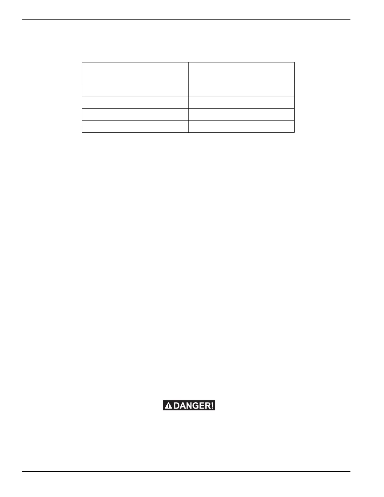
Table 6-3. Control Wire Length/Size
Maximum
Wire Length
Recommended
Wire Size
1-115 ft (1-35m) No. 18 AWG
116-185 ft (36-56m) No. 16 AWG
186-295 ft (57-89m) No. 14 AWG
296-460 ft (90-140m) No. 12 AWG