Gaseous Fuel Systems
18 Installation Guidelines for Spark-Ignited Stationary Emergency Generators
between the rigid supply piping and the gas connection at the generator, and must be installed straight without bends
or kinks. The primary regulator outlet and the generator connection point must be sized correctly to provide the gener-
ator with the required volume and pressure when it is operating at 100% of its rated load.
On the generator the unit mounted regulator (it may be either a demand regulator or a pressure regulator) and its asso-
ciated shutoff valves control the flow and pressure to the unit for proper operation. The fuel pressure required for the
generator to operate is always measured at the inlet of the unit mounted regulator. For the location of the pressure test
connection, see Subsection 5.6.1. The supply pressure and volume must meet the requirements described in the unit
specification sheet. If specifications are not met, the generator will not operate properly and will probably display symp-
toms, such as hard starting, rough running, inability to carry load, and erratic operation.
NOTE: Gas pressure from the primary regulator (supplied by the installing contractor) to the generator's fuel shutoff
valve should be between 5-14 inches W.C.
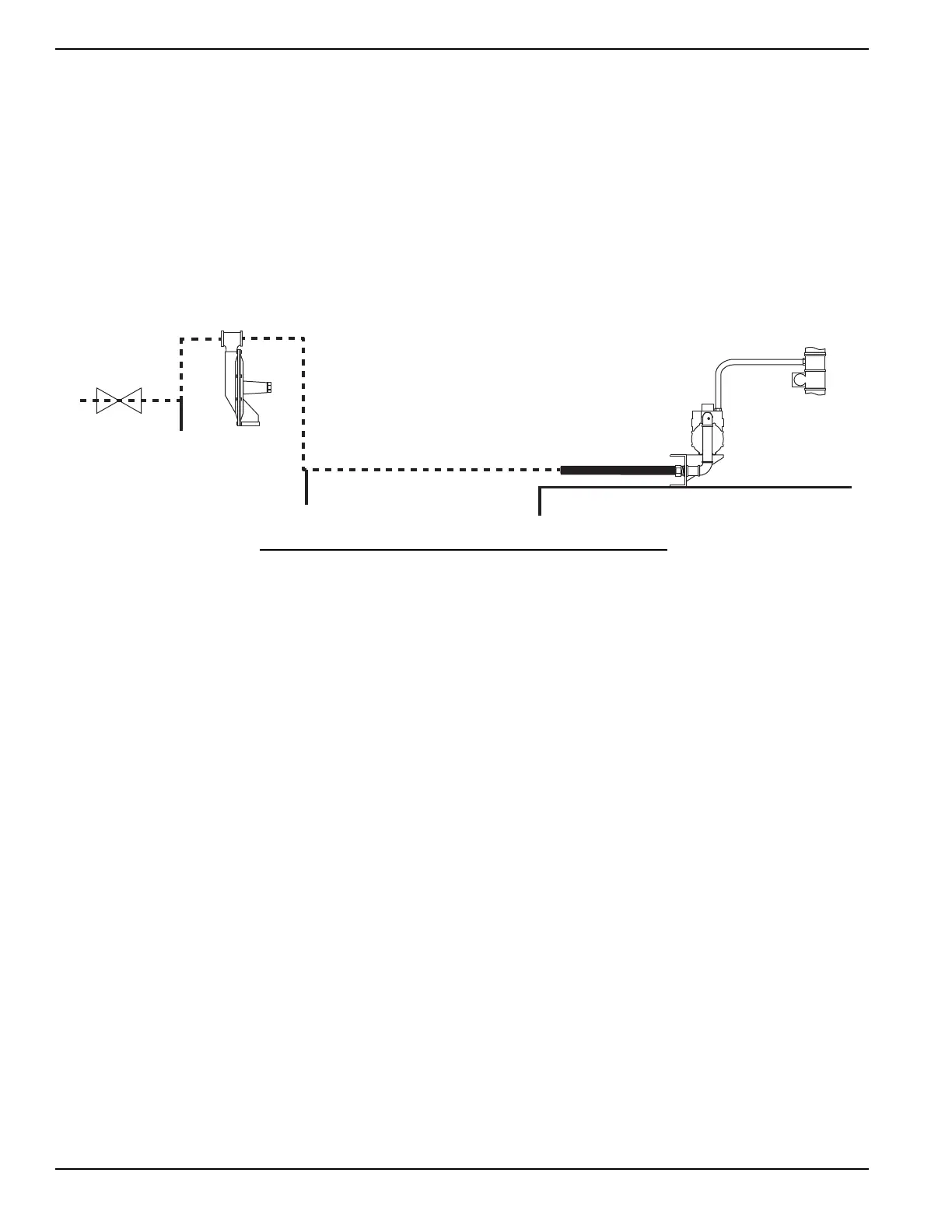
Figure 5-1. Typical NG Fuel System
5.3.2— LP-Vapor Withdrawal System
This type of system uses the vapors formed above the liquid fuel in the supply tank. The maximum tank fill capacity is
80% and a minimum of approximately 20% of the tank capacity is needed for fuel expansion from the liquid to vapor
state. Gas pressure and volume requirements for an LP-Gas vapor system at the connection point of the generator are
listed on the unit specification sheet.
Pressure regulation for vapor withdrawal systems is typically a two-step process. First, by reducing the high tank pres-
sure to a lower line pressure with a first-stage regulator, then reducing the line pressure to the pressure required by the
unit with a second-stage regulator. Both regulators and the associated system piping and valves need to be sized cor-
rectly to provide the generator with the required volume and pressure of fuel at the generator connection point.
NOTE: Gas pressure from the primary regulator (supplied by the installing contractor) to the generator's fuel shutoff
valve should be between 5-14 inches W.C.
Drip Leg
Drip Leg and Sediment Trap
Primary Regulator
Actuator
Flexible Fuel Line
Generator Base
Full Flow
Shut Off Valve
Unit Mounted
Regulator
The piping system between the primary
pressure regulator and the generator must
be properly sized to provide the fuel volume
required at 100% load while also staying
within the pressure range noted on the unit
specification sheet.
Follow the regulator manufacturer's recom-
mendation for placement and mounting of
the regulator.
 Loading...