Gaseous Fuel Systems
Installation Guidelines for Spark-Ignited Stationary Emergency Generators 19
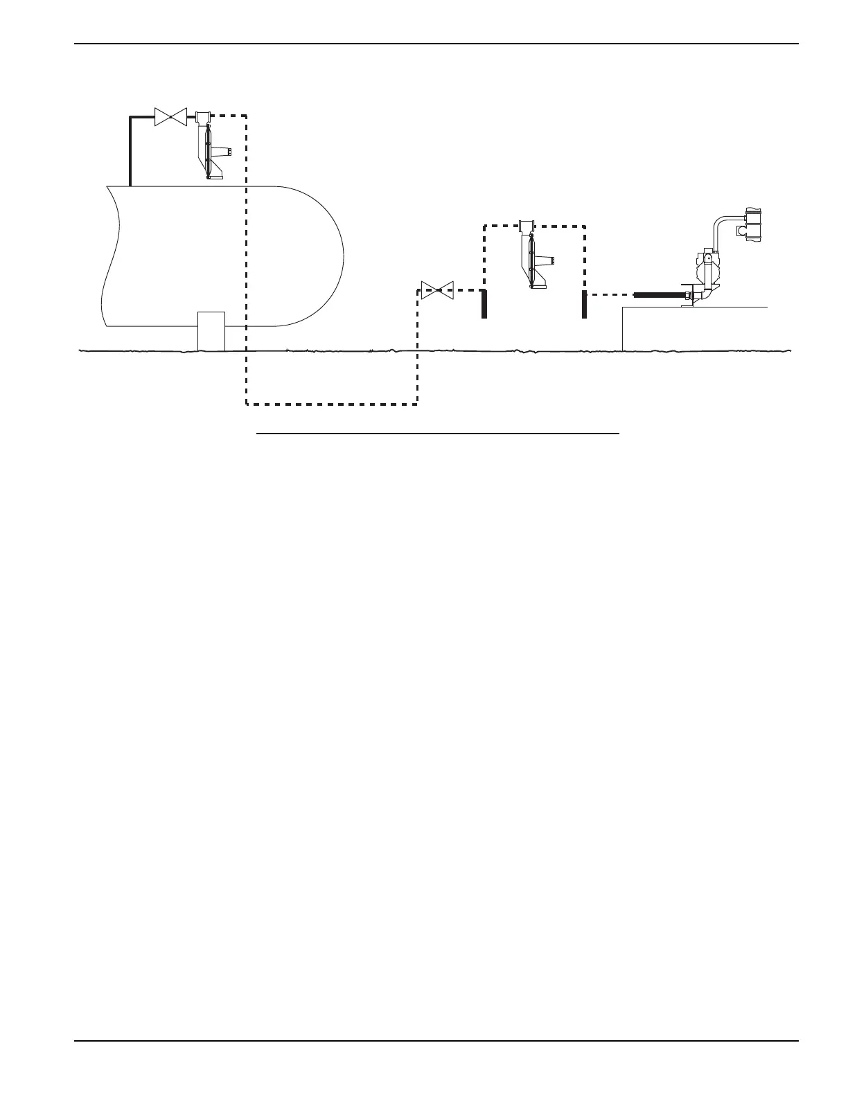
Figure 5-2. Typical LP-Vapor Withdrawal Fuel System
5.3.3— Drip Leg
Install at least one drip leg (sediment trap) before the unit to separate sediment, debris, and condensation from the gas
flow. A drip leg is also recommended at the bottom of a vertical pipe run and after each change in direction. Drip legs
protect downstream equipment, such as the primary or second stage pressure regulators, from clogging and contami-
nation. Some installations and/or jurisdictions may require no drip legs, or multiple drip legs. Consult the local AHJ for
requirements.
5.4 — Fuel Pressure Regulators
5.4.1— General
One of the most common causes of a generator set not operating properly is improper sizing and installation of the
gaseous fuel supply system between the meter (utility source) and the generator connection. The fuel supply system
consists of a primary regulator to regulate the flow and volume from the source (utility supply) to the generator, and all
of the associated piping, fittings, and shutoff valves, both upstream (feeding the main meter/regulator) and downstream
(between the meter and primary regulator), which connect the fuel source to the connection point on the generator. The
fuel supply system must be capable of supplying the correct volume of fuel within the correct pressure range to the
connection point on the generator. The volume of fuel and operating pressure required are listed in the technical spec-
ifications for the applicable generator. Fuel pressure at the unit must remain within the specified operating range and
not drop below the minimum pressure specified.
Drip Leg and
Full Flow
Shut Off Valve
Full Flow
Shut Off Valve
Flexible Fuel Line
Generator Base
Fuel Tank
Mixer
Unit Mounted
Regulator
Second Stage
Regulator
First Stage Regulator with
Relief Valve and Pressure Tap
The piping system connecting the outlet of the first stage regulator to the
connection point on the second stage regulator must be properly sized to
provide the fuel volume required by the unit at 100% load.
The piping system between the outlet of the second stage regulator and
the generator connection point must be sized to provide the fuel volume
required by the generator at 100% load while also staying within the pres-
sure range noted on the unit specification sheet.
Follow the regulator manufacturer's recommendation for placement and
mounting of the regulator.
Sediment Trap
Drip Leg and
Sediment Trap
 Loading...