Gaseous Fuel Systems
26 Installation Guidelines for Spark-Ignited Stationary Emergency Generators
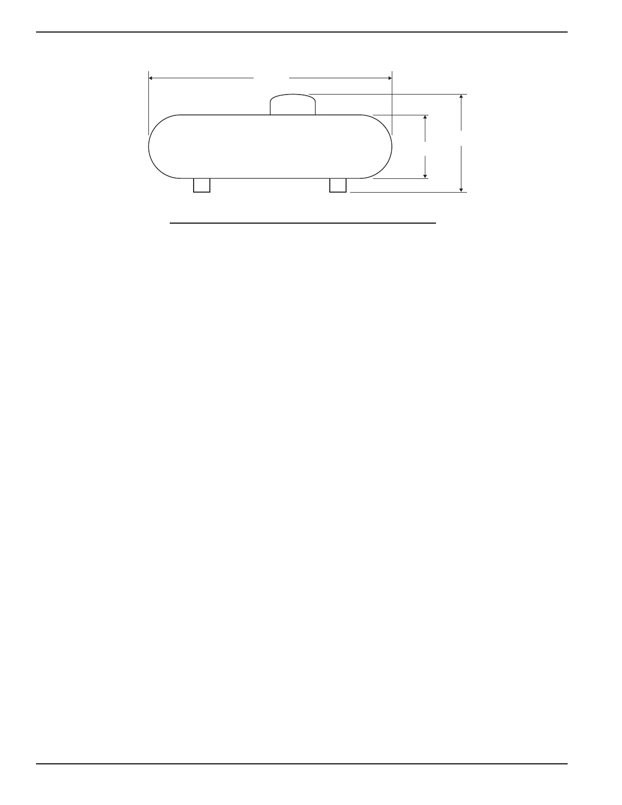
Figure 5-3. Typical Propane Tank Dimensions
NOTE: The minimum LP tank size is 250 gallons, unless unit calculations dictate use of a larger tank. Vertical tanks, which
are measured in pounds, will not usually meet the minimum tank size (250 Gallons x 4.20 Pounds = approximately a 1050
pound vertical tank minimum).
Propane conversion figures:
5.6 — Final Operating Test
A properly configured and sized fuel system provides the fuel volume and fuel pressure required for the generator set
to operate correctly in all modes of operation. To confirm proper fuel system operation, a series of tests must be per-
formed as further described below.
5.6.1— Gas Pressure Test Port Location
Using a suitable pressure gauge or water manometer, measure the gas pressure to the generator at a test port located
before the fuel solenoid shutoff valve(s).
See A of Figure 5-4. On units using the demand type regulator(s), there may be a factory installed 1/8 inch pipe port in
a tee fitting connected to the low pressure switch.
See B of Figure 5-4. If the unit has a low pressure switch without the tee, install a tee and plug between the low pres-
sure switch and the test port on the regulator body using a suitable pipe dope. Use only the upper port on the regulator
body, as it detects supply gas pressure even when the unit solenoid valve is closed. This allows static pressure to be
measured, as well as pressure when cranking, while running at no load, and while running at full load.
See C of Figure 5-4. Factory installed at the test point, some units may be provided with a special test port plug known
as a “Pete’s Plug.” The plug allows fuel pressure test readings to be taken quickly without leaving costly gauges
installed in the line.
Use the “Pete’s Plug” as follows:
1. Clean and lubricate gauge adapter probe with a small amount of petroleum jelly or silicone grease.
2. Assemble gauge adapter.
3. Using the appropriate sealant, screw barbed fitting into gauge adapter.
4. Install fuel hose of the proper pressure gauge onto barbed fitting.
5. Slowly unscrew protective cap from the test port plug.
NOTE: Quickly tighten the cap if escaping gas or liquid is heard or felt. Replace the plug if defective.
6. Insert gauge adapter into test port plug and secure.
7. Once the fuel pressure reading is obtained, remove gauge adapter probe and screw protective cap onto fuel
pressure test port plug.
NOTE: Take necessary readings as quickly as possible. Severe deformation of the valves may occur if gauge
adapter probe is left in the test port plug for a period of hours or days.
• 36.38 ft
3
= 90,500 Btu = 1gal • 1 lb = 21,500 Btu = 8.56 ft
3
• 2500 Btu = 1 ft
3
Propane
Length
Diameter
Height