Lube Oil Maintainer System
42 Installation Guidelines for Spark-Ignited Stationary Emergency Generators
NOTE: When changing engine oil, always close the shutoff
valve to avoid draining the clean oil in the oil supply tank with
the crankcase oil. See Figure 7-3
7.1.2— Fill Oil Supply Tank
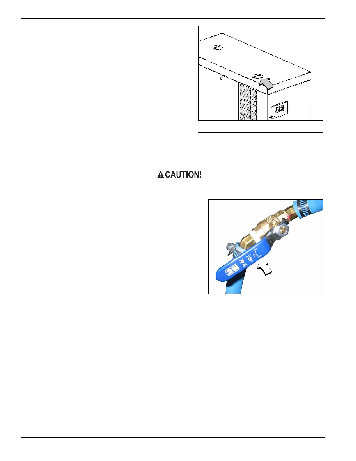
1. Rotate plastic cover counter-clockwise and remove from top
of enclosure. See Figure 7-2
2. Remove fill cap at top of oil supply tank (Figure 7-2).
3. Add clean engine oil to oil supply tank (2-1/2 gallons [9.46
liters] capacity).
4. Install fill cap at top of oil supply tank.
5. Install plastic cover at top of enclosure and rotate clockwise
until tight.
7.1.3— Test Functionality
See A of Figure 7-1 Momentarily press the test button to confirm that the float is operating correctly.
Do not hold the test button down for a prolonged period of time or the crankcase can be over filled. Over
filling the crankcase can result in engine damage.
7.1.4— Shutoff Valve
See Figure 7-3 and Figure 7-4 When draining engine crankcase
oil, always close shutoff valve to avoid draining clean oil from sup-
ply tank.
After filling crankcase with clean oil, remember to open shutoff
valve to enable operation of Lube Oil Maintainer System.
Figure 7-2. Access Oil Supply Tank
Figure 7-3. Shutoff Valve
(Shown in Open Position)
 Loading...