Electrical System
30 Installation Guidelines for Spark-Ignited Stationary Emergency Generators
NOTE: The following tables are provided for references purposes only. Refer to the latest NEC, state and local
AHJ requirements for proper sizing of power and control wires.
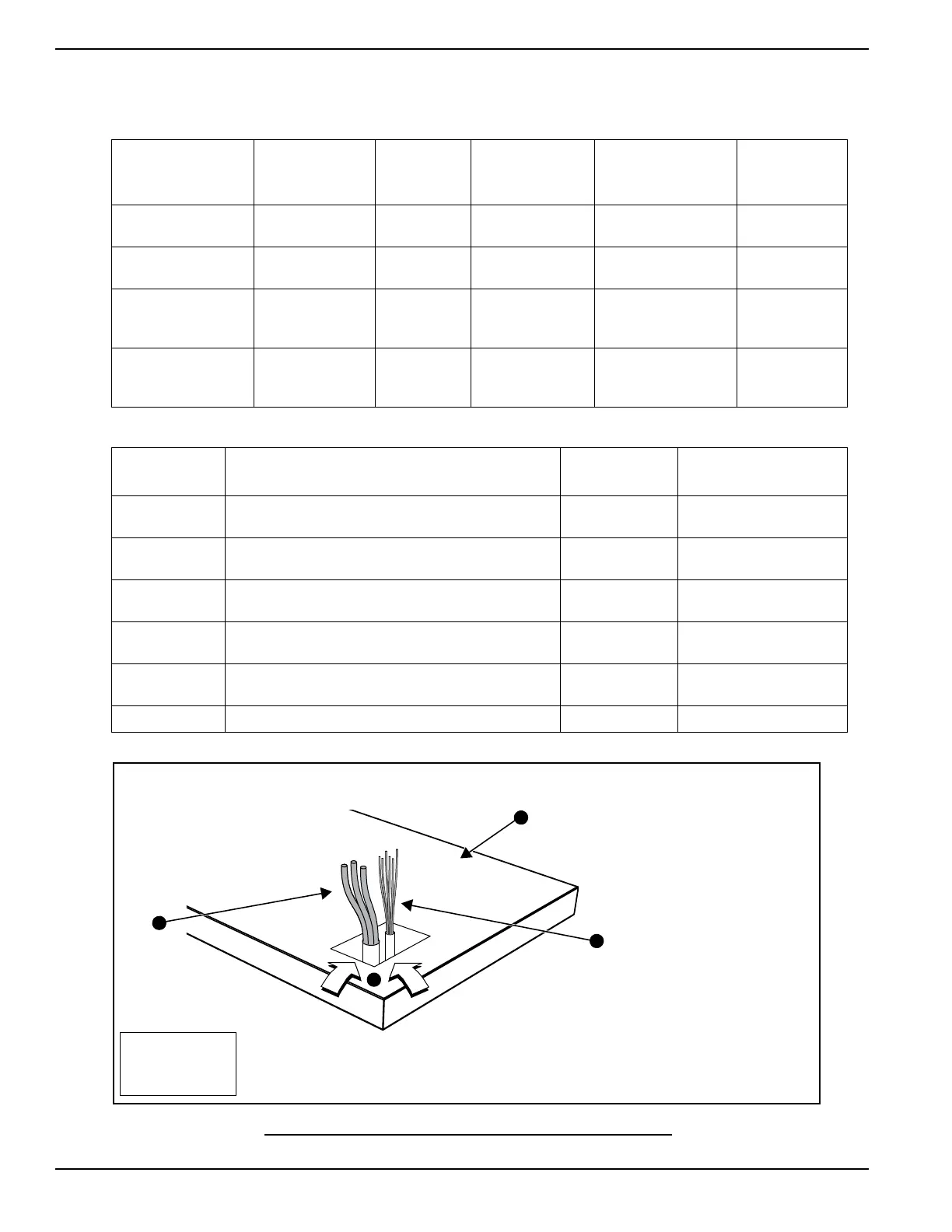
Figure 6-2. Typical Load Leads and Control Wiring in Stub Up
Table 6-1. Frame Breakers
Frame Breaker Range Wire Type
Wire
Temperature
Rating
Lug AWG Range
(Number of
Conductors)
Torque
to Wire
Generac 225 AF
2 Pole
125A-200A Cu/Al 167º F (75º C) 6-350 kcmil (1) 375 in-lb
Generac 225 AF
3 Pole
50A-200A Cu/Al 167º F (75º C) 6-350 kcmil (1) 375 in-lb
Generac 400 AF
2 Pole
225A-400A Cu/Al 167º F (75º C)
1/0-250 kcmil (2)
or
4-600 kcmil (1)
375 in-lb
Generac 400 AF
3 Pole
225A-400A Cu/Al 167º F (75º C)
1/0-250 kcmil (2)
or
4-600 kcmil (1)
375 in-lb
Table 6-2. Terminal Tightening Torques
Amperage
Rating
Description
Cable Screw
Torque
Wire Size Range
15-20 A Load Side, Aluminum Body Lug 32 in-lb
#14 - #8 AWG Cu
#12 - #8 AWG Al
25-35 A Load Side, Aluminum Body Lug 36 in-lb
#8 - #6 AWG Cu
#8 - #6 AWG Al
40-50 A Load Side, Aluminum Body Lug 45 in-lb
#8 - #6 AWG Cu
#8 - #4 AWG Al
55-70 A Load Side, Aluminum Body Lug 50 in-lb
#8 - #4 AWG Cu
#8 - #2 AWG Al
80-100 A Load Side, Aluminum Body Lug 60 in-lb
#4 - #1/0 AWG Cu
#2 - #1/0 AWG Al
10-130 A Line Side, Threaded Contact With Ring Lugs 72 in-lb #14 - #2 AWG
NOTE: Refer to specific NEC
article for routing of control
wires and power wires. AHJ
has final call on single or
dual conduit.
NOTE: Stub up area shown
is for reference only. See
installation drawings for unit
specific details.
A = Load Leads
B = Control Wiring
C = Stub Ups
D = Concrete Pad
A
 Loading...