Gaseous Fuel Systems
Installation Guidelines for Spark-Ignited Stationary Emergency Generators 23
There are several pipe sizing programs available for use on the Internet and from various manufacturers. If used it is
highly recommended that the minimum pressure drop value always be used (0.5 inches w.c or less). This will ensure
that the piping system is sized correctly to handle the generator set volume at full load, and during cranking and load
transients, while also remaining above the minimum operating pressure.
The following general rules apply to piping of gaseous fuel systems:
• Use black iron piping or other approved gas line. Pipe must be rigidly mounted and protected against vibration.
• Install the supplied or recommended length of flexible hose between the generator connection point and the rigid
supply piping. Install the flexible hose straight without bends, twists or kinks. Do not install the flexible hose
underground or in contact with the ground.
• Install a drip leg and sediment trap. (Consult local AHJ for requirements)
• Correctly size the piping to maintain the required supply pressure and volume under varying load conditions.
• Properly purge and leak test installed piping.
• Use an approved pipe sealant or joint compound on all threaded fittings to reduce the possibility of leakage.
• Make provision for a fuel shutoff valve near the unit. Verify that the fuel shutoff valve is installed correctly and
works properly.
• Using suitable methods, check entire pipe run for leaks.
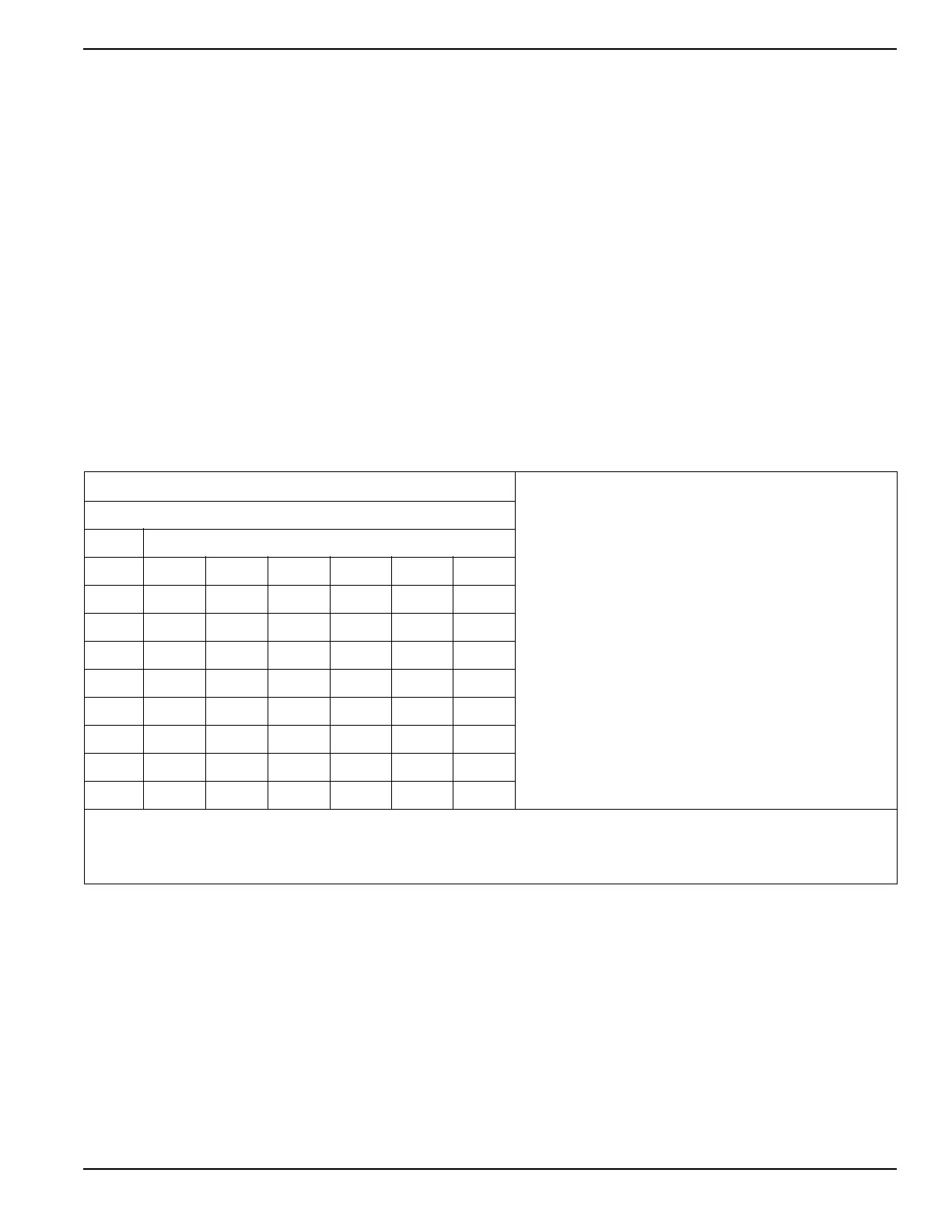
Table 5-2. Fuel Pipe Sizing for Natural Gas (NG)
Natural Gas 5" to 14" of Water Column
Natural Gas
1 cubic foot = 1,000 BTU
1 therm = 100,000 BTU
Gas consumption = 13,000-16,000 BTU per kW/hr
Pressure
1 inch mercury = 13.61 inches water column
1 inch Water Column = 0.036 psi
3.5–14 inches water column = 0.126 psi to 0.50 psi
Note:
• Pipe sizing is based on 0.5" H
2
O pressure drop.
• Sizing includes a nominal number of elbows and tees.
• Please verify adequate service and meter sizing.
• Tables based on black pipe.
Table values are maximum pipe run in feet.
Pipe Size (inches)
kW 1 in 1.25 in 1.5 in 2 in 2.5 in 3 in
22 20 100 200 750 — —
25 10 80 175 575 — —
27 — 85 203 552 — —
30 — 60 125 450 — —
35-36 — 35 95 370 915 —
45 — 15 60 260 650 —
48 — — 50 230 585 —
60 — — 25 145 375 1100
Note: Size the fuel pipe to the sizing charts or to local codes. When installing other than Sch. 40 black pipe, please refer to the manufactures
sizing charts.
The liquid-cooled generator is not a constant flow appliance, the fuel pipe was sized large enough to supply at least 125% of the generator BTU/hr
rating.
 Loading...