Operation
36833 C MGG100M Operating Manual 31
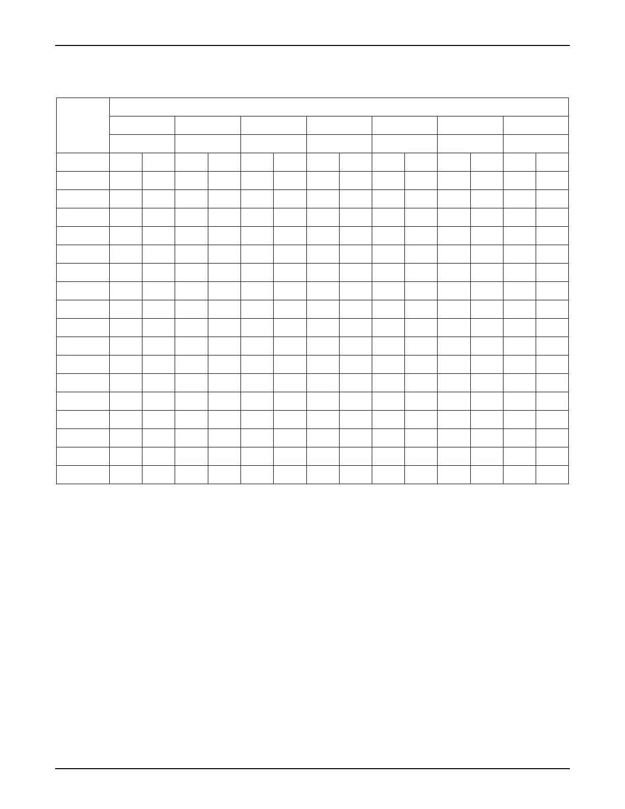
Use the charts as follows.
1. Locate required flow in the left hand column. If it falls between two numbers, use the larger.
2. Determine total required pipe length.
3. Read chart from left to right to find the total length equal to or greater than the distance from source to use.
4. From that point, read up to find the required pipe size.
Table 2 - LP Liquid Line Sizing Chart
Liquid
Propane
Flow
Iron Pipe Size (Diameter)
1/4” 3/8” 1/2” 3/4” 1” 1-1/4” 1-1/2”
Schedule Schedule Schedule Schedule Schedule Schedule Schedule
GPH 4080408040804080408040804080
10 729 416
15 324 185
20 182 104 825 521
40 46 26 205 129 745 504
60 20 11 92 58 331 224
80 11 6 51 32 187 127 735 537
100 7 4 33 21 119 81 470 343
120 23 15 83 56 326 238
140 15 9 61 41 240 175 813 618
160 13 8 47 32 184 134 623 473
180 37 25 145 106 491 373
200 30 20 118 86 399 303
240 21 14 81 59 277 211
280 15 10 60 44 204 155
300 13 9 52 38 177 135 785 623
350 38 28 130 99 578 459
400 30 22 99 75 433 344 980 794
 Loading...