EasyManuals Logo

Generac Power Systems Magnum MGG100M User Manual

Generac Power Systems Magnum MGG100M
84 pages
To Next Page IconTo Next Page
To Previous Page IconTo Previous Page
Page #20 background imageLoading...
Page #20 background image
General Information
12 MGG100M Operating Manual 36833 C
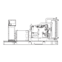
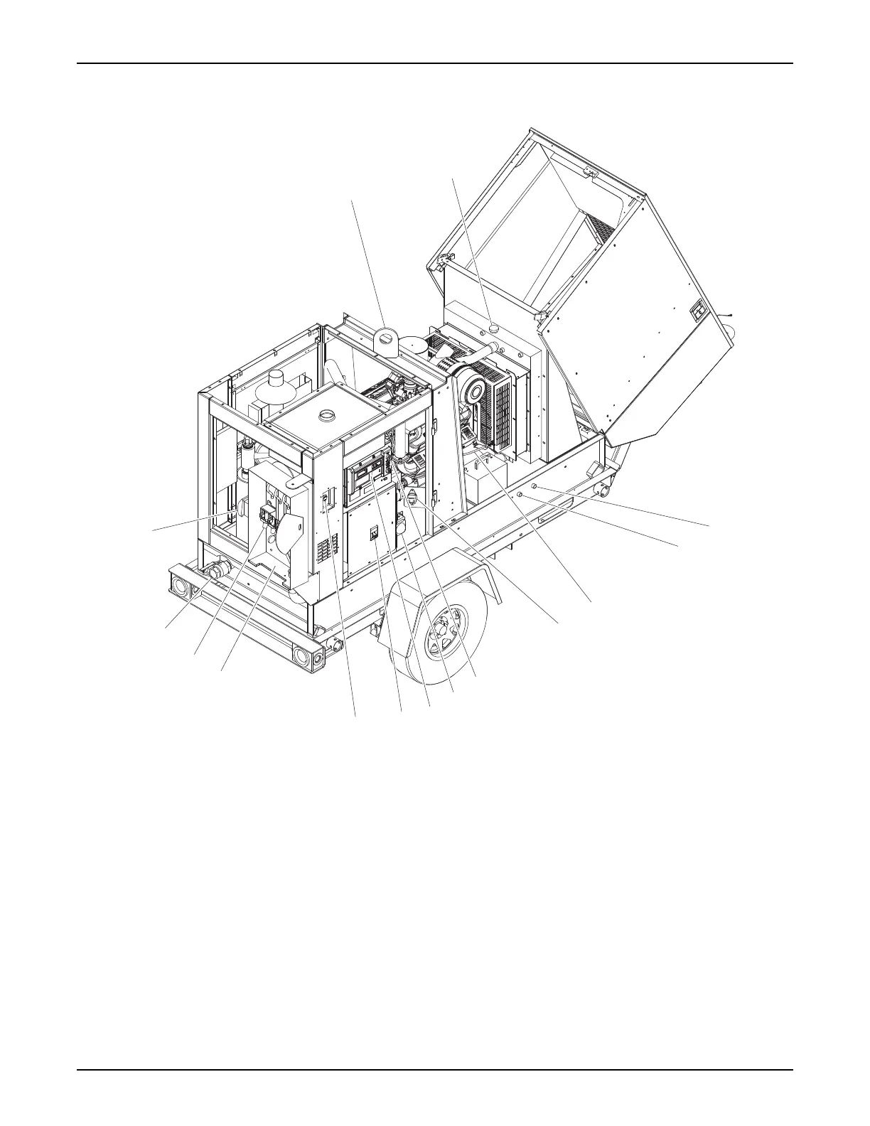
Right Side
Figure 6 - Component Locations, Right Side
1. Central lift point 8. Oil level controller
2. Coolant pressure cap 9. H-100 controller
3. Coolant drain 10. Main circuit breaker (MLCB)
4. Engine oil drain 11. Customer disconnect switch box
5. Dipstick 12. Connection lugs with cam locks
6. Battery disconnect switch 13. NG inlet port
7. Emergency stop switch 14. Customer convenience receptacle
01199
1
2
5
3
6
4
7
8
9
10
7
11
12
13
14

Table of Contents

Questions and Answers:

Question and Answer IconNeed help?

Do you have a question about the Generac Power Systems Magnum MGG100M and is the answer not in the manual?

Generac Power Systems Magnum MGG100M Specifications

General IconGeneral
BrandGenerac Power Systems
ModelMagnum MGG100M
CategoryInverter
LanguageEnglish

Related product manuals