6 Owner’s Manual for Power Zone Pro Sync
General Information
Voltage Regulation (Single or Three-Phase
Module Options)
• Digital Control
• Single-Phase or Three-Phase RMS Sensing with
Loss of Sensing Protection
• Variable V/F Slope Settings and Adjustable Gains
• Negative Power Protection
• Soft Start Ramping
• Paralleling Function
• Fault Protection (I
2
T Function and GFI)
PLC (Built-In Programmable Logic
Controller)
• Configurable Through Software Tool
• Customer Configurable for Non-Standard Options
• Up to 8 PLC Programs Run Simultaneously or in
Sequence
Governor Module
• Soft Start Ramping
• Synchronizing Function (if equipped)
• Fully Adjustable Gains (PID)
Connections
• 27 Digital Outputs Maximum (Open Drain, 35 V
1.7 A)
• 6 fast PWM capable outputs 1 High Current
• 26 Digital Inputs Maximum
• 6 fast PWM capable inputs
• 12 General Purpose Analog Inputs
• 4 Special Purpose Analog Inputs
• 4 Analog Outputs (0-10 V )
• 1 E-Stop Relay Output
• 7 Current Sense Inputs
• 8 High Voltage Sense Inputs (Three (3) Phase +
Neutral)
• 2 Magnetic Pickup Inputs
• 1 Coolant Level Sensor Input
• 4 RJ-45 Controller Network Ethernet Ports
• 1 RJ-45 External Ethernet Port
• 3 CAN bus Channels
• 1 RS-485 Port
• 2 Switchable 12 V Power Outputs
NOTE: Actual I/O may vary due to configuration.
Qualification Testing
• Life Test in Environmental Chamber
• Temperature Rating
• Humidity
• Vibration Tested and Protected
Codes and Standards
• UL 6200 Investigation of Controls for Stationary
Engine Driven Assemblies
• UL 2200 Standard for Stationary Engine Generator
Assemblies
• CSA STD C22.2 No. 14
• EN 61010-1 Safety Requirements for Electrical
Equipment for Measurement, Control, and Labora-
tory Use
• EN 61000-6-2 EMC Immunity for Industrial Envi-
ronments
• EN 61000-6-4 EMC Emissions Standard for Indus-
trial Environments
• NFPA 110 (configurable for Level 1 or 2) (with
additional optional remote annunciator)
• NFPA 70 National Electrical Code for Safe Electri-
cal design, Installation, and Inspection
• IEC801 Radiated Emissions, Susceptibility and
Surge Immunity
• FCC and IC Canada (for Display only)
Protections
• Sender Failure
• Low Oil Pressure
• Low Coolant Level
• High/Low Coolant Temperature
• High/Low Oil Temperature
• Over/Under Speed
• Over/Under Voltage
• Over/Under Frequency
• Over Current
• Over Total kW
• High/Low Battery Voltage
• Battery Charge Current
• Phase to Phase and Phase to Neutral Short
Circuits (I
2
T Algorithm and GFI)
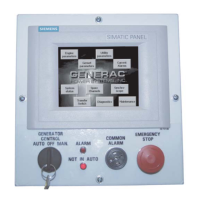
Control Panel and Touch Screen
• Auto/Manual/Off
• Alarm Acknowledge Button
• Audible Alarm
• Emergency Stop


 To Next Page