Owner’s Manual for Power Zone Pro Sync 23
Operation
Section 3 Operation
Connection Description
If the system is equipped with all of the Power Zone Pro
Sync controller options installed, the controller will be
connected in the following ways: Each generator will
house a Main Controller, a Governor, an AVR/3PAVR, a
Battery Charger, and a Display. The Main Controller,
Governor, AVR/3PAVR, and Battery Charger all
communicate to one another through one continuous
CAN bus chain. The Governor and AVR/3PAVR are
powered by the Main Controller. The Main Controller is
powered by the Battery Charger or the Battery. The
Battery Charger is powered by the utility. The Display is
included on each generator. It communicates with the
Main Controller over Ethernet port 1. The Display is
powered by the Main Controller. In a system with multiple
generators, each Main Controller is connected to the next
via Ethernet port 2 or 3.
Each generator in a Power Zone Pro Sync system will
likely have its own RAP(s), most commonly located in a
control room inside the building. In addition to the
individual RAP(s) for each generator, one or more RAPs,
known as System RAPs, will likely be in the system.
Every RAP is connected to one another through a non-
powered Ethernet switch. One of the Main Controllers
connects to this non-powered Ethernet switch to
communicate with all members connected to the switch.
A P&L connects to this non-powered Ethernet switch with
its own Ethernet connection, as all RAPs and the P&L
rely on information from the Main Controllers to operate
normally.
NOTE: The P&L should have two Ethernet connections.
NOTE: The number of transfer switches and their
locations may differ with each site. Generally, every site
should have at least one transfer switch. Refer to the
transfer switch Owner’s Manual for further clarification on
its operation and maintenance.
Setup for Backup Mode in MPS
A system with two or more generators running in parallel
can be configured to run in Backup Mode if communica-
tion between Controllers is lost. In Backup Mode, dead
bus arbitration is provided and the generators run in
Droop.
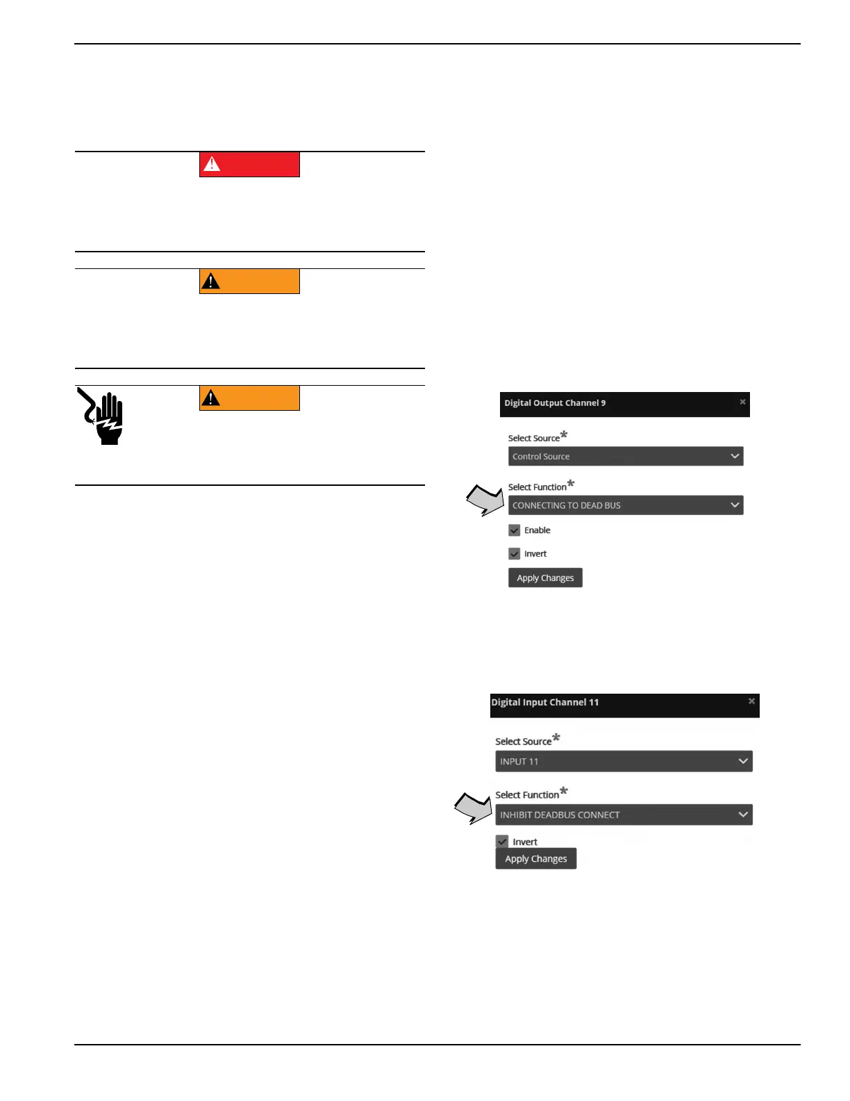
1. See Figure 3-1. Program Digital Output #9 on
Gen1 for “CONNECTING TO DEAD BUS”.
Figure 3-1. Program Digital Output
2. See Figure 3-2. Program Digital Input #11 on
Gen2 for “INHIBIT DEADBUS CONNECT”.
Figure 3-2. Program Digital Input
3. Verify interconnect wiring includes a wire from
GEN1 TB2-2Y (Connecting to Dead Bus) to GEN2
TB2-4Y (Inhibit Dead Bus Connect). This will pre-
vent Gens 1 and 2 from closing to the dead bus at
the same time.
(000190)
DANGER
Loss of life. Property damage. Installation must
always comply with applicable codes, standards, laws
and regulations. Failure to do so will result in death
or serious injury.
(000182a)
WARNING
Equipment damage. Only qualified service personnel may
install, operate, and maintain this equipment. Failure to
follow proper installation requirements could result in death,
serious injury, and equipment or property damage.
WARNING
Electrocution. More than one live high voltage
circuit is present. Disconnect all power
sources before servicing. Failure to do so
could result in death or serious injury.
(000563)