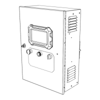
Owner’s Manual for Power Zone Pro Sync 9
General Information
System Components
Figure 2-1. System Components
A Power Zone Pro Sync Display Screen L Control Panel Harness
B Emergency Stop Switch M Internal Relay Boards
C Alarm Horn N DC Fuses
D AUTO/OFF/MANUAL Keyswitch O Customer Relay Board
E Governor Driver (if equipped) P Generator/Utility Voltage Sense
F Customer Terminal Connections Q Battery Charger (if equipped)
G Battery DC Connection R AVR Driver (if equipped)
H Battery Charger AC Connector S Deutsch Engine Interface Connector
I Current Transducer (CT) Connection T Starter Contactor
J
Circuit Breaker Control and Alternator
Connections
U Control Cabinet
K Main Controller
A
B
R
S
T
K
009363
D
C
L
E
Q
F
P
G
H
I
J
U
O
M
N

 Loading...