Owner’s Manual for Power Zone Pro Sync 15
General Information
Customer Connections
The following customer connections are available:
• BMS (Building Management System)
• Relay Boards
• Run Relays (If Equipped)
• Utility Connection
• Remote Emergency Stop (If Equipped)
• RAP (Remote Annunciator Panel) and RRP
(Remote Relay Panel) (If Equipped)
• Interconnect Diagram
BMS (Building Management System)
A BMS can monitor and partially control a Power Zone
Pro Sync generator via Ethernet connection to the
Display being used on that generator. Communication
between the generator controllers and the BMS can be
achieved via Ethernet or RS-485. For RS-485, a USB
converter is required.
Relay Boards
The Power Zone Pro Sync System uses two types of
relay boards: the internal control relay board and the
customer connection relay board. The main difference
between the two boards is the customer connection relay
board has extra surge protection due to the unknown
properties of the potentially connected devices or circuits.
Otherwise, the control signals and the contacts behave in
the same manner. The relay boards are either 12 V or
24 V nominal.
IMPORTANT NOTE: Verify the relay board voltage
matches the coil power source voltage to prevent
damage to the relays and provide reliable coil
activation.
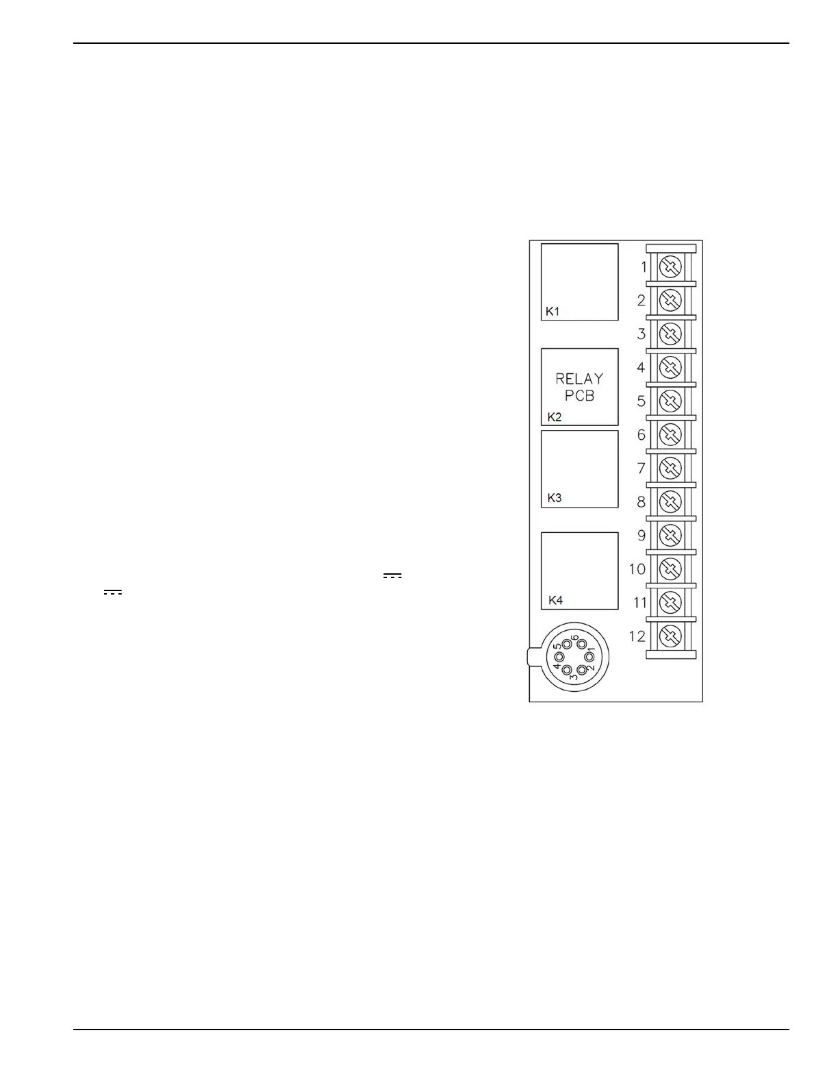
There are four relays (K1-K4) per relay board in groups
of two relays sharing one coil power source for their coils.
K1 and K2 share the coil power source connected to A-1.
K3 and K4 share the coil power source connected to A-4.
The coil control signals are A-2 for K1, A-3 for K2, A-5 for
K3, and A-6 for K4. The coil is activated when the control
signal is grounded. Each relay is connected to three
screw terminals. The first terminal is a normally open
(N.O.) contact to the common (COM). The second
terminal is a normally closed (N.C.) contact to the
common (COM). The third terminal is the common
(COM). K1 is connected to terminals 1-3, K2 is
connected to terminals 4-6, K3 is connected to terminals
7-9, and K4 is connected to terminals 10-12.
The internal control relays are wired differently
depending on the configuration of the generator. They
will control fuel shutoff solenoids, starter contactors,
power to peripherals, etc. Refer to the wiring diagram for
your particular system for details.
The customer relay board is typically connected such
that the Main Controller DOUT #17 (Pin BS3-17) is
connected to control signal A-2, DOUT #18 (Pin BS3-18)
is connected to control signal A-3, DOUT #19 (Pin BS3-
19) is connected to control signal A-5, and DOUT #20
(Pin BS3-20) is connected to control signal A-6. These
outputs can be configured via the Power Zone Pro Sync
Display to provide the desired customer relay
functionality.
Figure 2-4. Relay Board