Owner’s Manual for Power Zone Pro Sync 25
Operation
NOTE: After disconnecting the Controller power or
Ethernet cable, the other units will display an “MPS
COMMS FAIL” warning message. The other units will be
in Backup Mode until the new Controller is installed and
programmed.
Upgrade the firmware in the new Controller and the
Display to the latest version:
14. Upgrade firmware in the Display and Controller to
the latest version from GenService.
Write the original configuration file to the new
Controller:
NOTE: Before writing configuration file, inspect for any
erroneous values.
15. See Figure 3-4. Select “Tools” (A).
16. Select “Configuration File Transfer”.
17. Select “Write to Controller”.
18. Select “Choose” and select the original file.
19. Select “Load”.
20. Delete old Controller from the “Device Manager”
screen on each Display and assign the new Con-
troller a Friendly Name.
21. See Figure 3-4. Select “Setup” (B).
22. Select “Communications”.
23. Select “Device Manager”.
24. Select “Clear Devices”. Repeat this step on ALL
other Displays in the system including P&L (Per-
missive and Loadshed) Displays.
25. Select the new entry titled “Main Controller”.
26. Select “Edit” and create a Friendly Name for this
Controller.
27. Select “Save”.
Configure the Controller in “Permissives and Load-
shed Setup” in the P&L (if equipped):
28. From any Controller, select “Setup” (Figure 3-4,
item B).
29. Select “Modules”.
30. Select “Permissives and Loadshed Setup”.
31. Find the old Controller and uncheck the check-
boxes for both “Include” and “Pin Connected”.
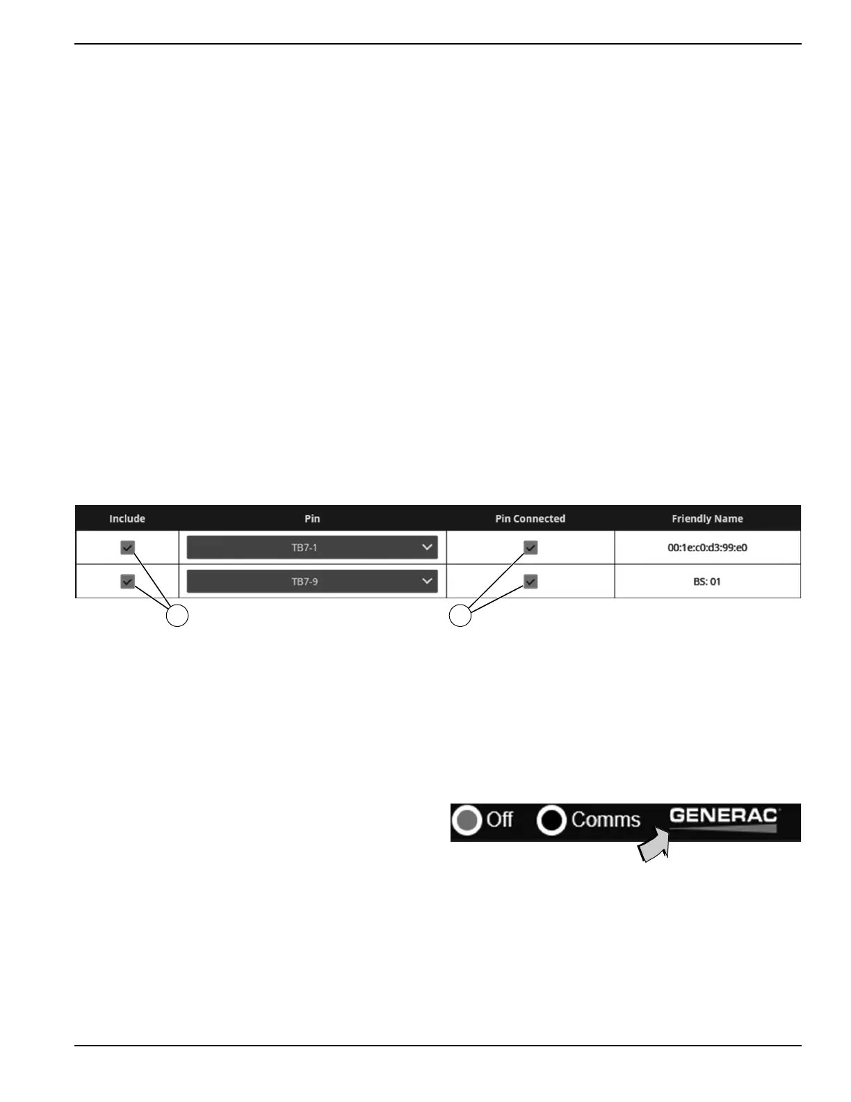
32. Find the new Controller and configure it on a pin.
See Figure 3-6. Check the checkboxes for
“Include” (E) and “Pin Connected” (F).
33. Select “Apply Changes” at the bottom of the screen
to save changes.
Figure 3-6. Configure Controller in the P&L
Verify “Number of MPS Generators” parameter in all
Controllers and check for any MPS alarms:
34. In each controller, verify the “Number of MPS Gen-
erators” parameter is set to the total number of
generators in your MPS. If it is not correct in any of
the Controllers, change it to the correct value.
35. See Figure 3-4. Select “Setup” (B).
36. Select “Setups”.
37. Select “System Setup”.
38. Verify there are no MPS alarms present on the
Alarm Log.
Final steps:
39. Run the unit to recalibrate voltage and current.
Replace the Power Zone Pro Sync Display
Replace the Display:
1. Remove the display and mount the new one (part
no. 10000007810).
2. Connect the power but do NOT connect the Ether-
net cable between the Controller and the Display.
Clear cache on the new Display:
3. Login to the Display.
4. See Figure 3-7. Select the Generac logo at the top
of the screen.
Figure 3-7. Select Generac Logo
5. Select the “Clear cached data” button to ensure the
new Display is reset to factory defaults.
Upgrade Display firmware to the latest version from
GenService:
6. Upgrade firmware in the Display to the latest ver-
sion from GenService.
NOTE: Do NOT proceed until completing step 6.