Owner’s Manual for Power Zone Pro Sync 17
General Information
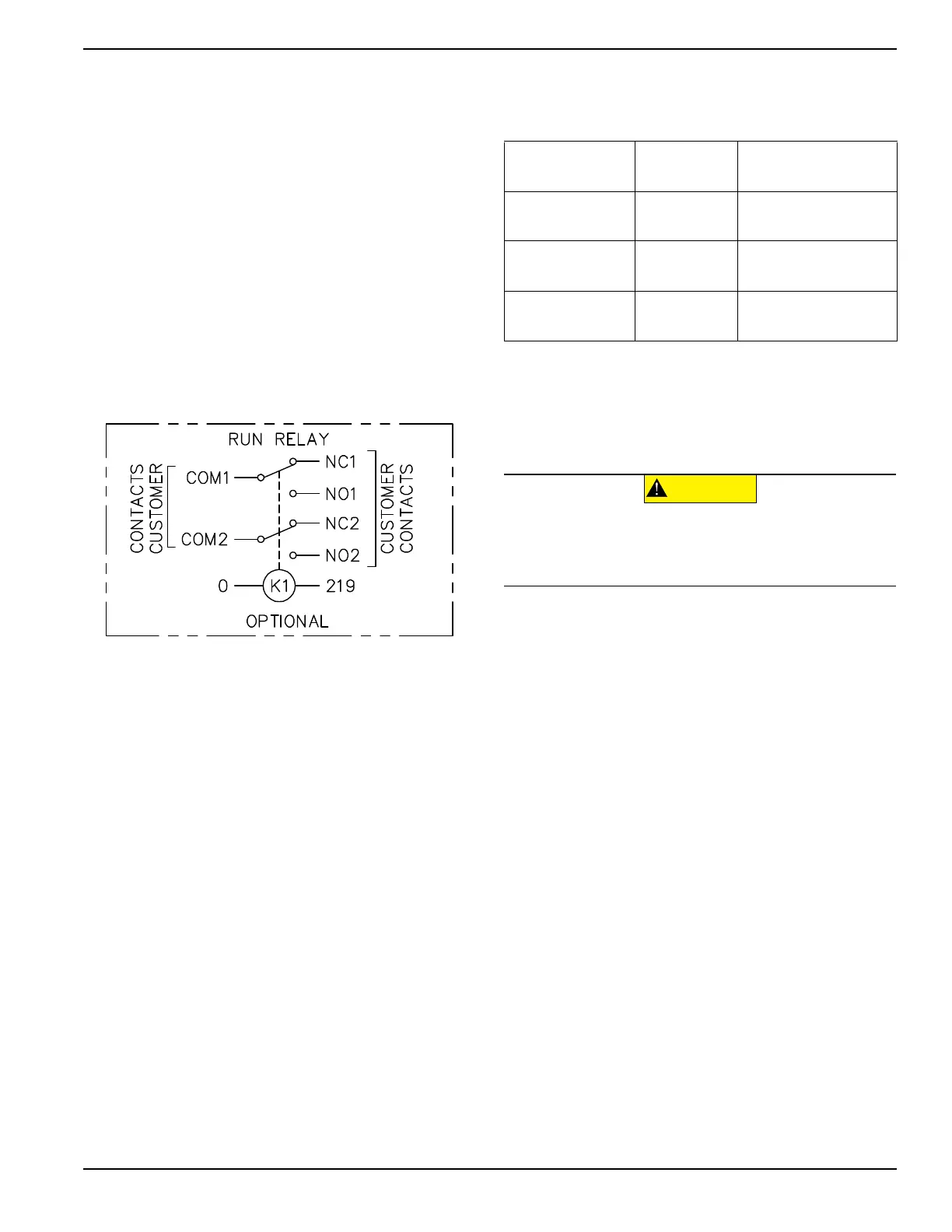
Run Relays (If Equipped)
The Power Zone Pro Sync System can have an optional
Run Relay installed. This is a two pole relay with two
separate commons, COM1 and COM2. There is a set of
contacts available for each common which includes a
normally open (N.O.) contact and a normally closed
(N.C.) contact. COM1 is associated with NO1 and NC1.
COM2 is associated with NO2 and NC2. The coil is
grounded on one side and connected to the “Fuel Relay”
circuit on the other. The coil is activated when the Fuel
Relay circuit is active. The Fuel Relay circuit is normally
activated when the generator starts to crank (timing
depends on startup relay settings) until the generator
begins to shut down (timing depends on shutdown relay
settings).
The customer can use these relay contacts to control
enclosure or room louvers, heaters, etc.
Figure 2-8. Run Relay Schematic
Utility Connection
A Power Zone Pro Sync system uses a utility connection
to the generator to supply power to the battery charger,
louver actuators, block heaters, enclosure heaters,
enclosure lighting, etc. This is normally done by
connecting utility to a Utility Load Center (if equipped)
and connecting the utility powered devices to the load
center breakers.
The utility supply connections are located in the Utility
Load Center breaker distribution panel near the back of
the generator. Depending on the current rating of the
terminal block used, the connector tightening torque
values and the acceptable wire ranges are listed in
Table 2-1.
NOTE: The current ratings are located directly on the
circuit breaker. The above information is rated for UL
acceptance.
Remote Emergency Stop (If Equipped)
All Power Zone Pro Sync generators are equipped with a
connection point for a remote emergency stop (E-Stop),
in series with the unit supplied E-Stop, that allows a user
or technician to shut down the generator remotely in the
event of an emergency (see Figure 2-1). If the E-Stop
was used to shut down a generator, the button must be
pulled back out, and the alarms must be reset to restart it.
Table 2-1. Connector Torque and
Acceptable Wire Range
Connector
Current Rating
Tightening
Torque
Acceptable Wire
Range
30 Amp
Connectors
5.5 in-lb
(0.6 Nm)
(1-2) 24-10 AWG
(CU)
50 Amp
Connectors
10.6 in-lb
(1.2 Nm)
(1-2) 22-8 AWG
(CU)
60 Amp
Connectors
18.0 in-lb
(2.0 Nm)
(1-2) 20-6 AWG
(CU)
CAUTION
(000246b)
Equipment Damage. The emergency stop switch is
not to be used to power down the unit under normal
operating circumstances. Doing so could result in
equipment damage.