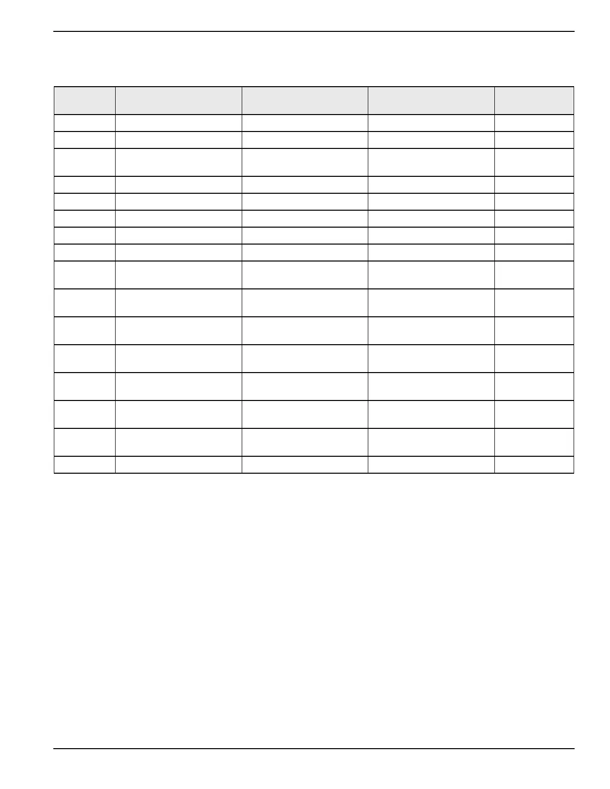
Table 3-5. J5 Connector
Pin Name Description
Configured Default
NA = Not Configurable
Wire # (Default)
(BS5) J5-1 DIN1 Digital Input. Configurable Auto Switch 174
(BS5) J5-2 DIN2 Digital Input. Configurable Manual Switch 175
(BS5) J5-3
DIN3 Digital Input. Configurable Ruptured Basin/Gas
Pressure
601
(BS5) J5-4 DIN4 Digital Input. Configurable E-Stop R15
(BS5) J5-5 DIN5 Digital Input. Configurable 2-wire Remote Start 183
(BS5) J5-6 DIN6 Digital Input. Configurable Battery Charger AC Fail 505
(BS5) J5-7 DIN7 Digital Input. Configurable Aux In #3 (Line Power) DI3
(BS5) J5-8 DIN8 Digital Input. Configurable Aux In #4 (Gen Power) DI4
(BS5) J5-9
DIN9 Digital Input or PWMI 0.
Configurable
Aux In #1 PWMI #0 DI1
(BS5) J5-10
DIN10 Digital Input or PWMI 1.
Configurable
Aux In #2 PWMI #1 DI2
(BS5) J5-11
DIN11 Digital Input or PWMI 2.
Configurable
Aux In #5 PWMI #2 DI5
(BS5) J5-12
DIN12 Digital Input or PWMI 3.
Configurable
Aux In #6 PWMI #3 DI6
(BS5) J5-13
DIN13 Digital Input or PWMI 4.
Configurable
Aux In #7 PWMI #4 DI7
(BS5) J5-14
DIN14 Digital Input or PWMI 5.
Configurable
Aux In #8 PWMI #5 DI8
(BS5) J5-15
DIN15 Digital Input or PWMI 6.
Configurable
AVR ZC - PWMI #6 406
(BS5) J5-16 N.C. No Connection
Owner’s Manual for Power Zone Pro Main Controller 19
Installation and Operation