Installing PWRcell Battery
Installation Manual for Generac PWRcell Battery 21
Placing Chassis onto Bracket and Leveling Feet
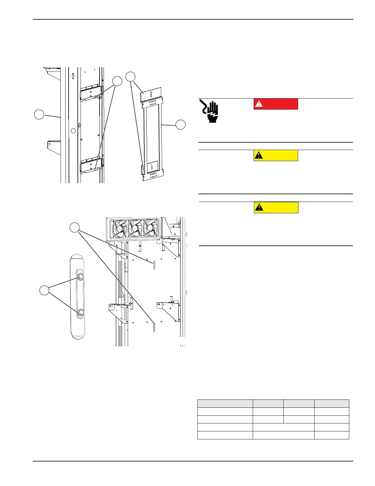
1. See Figure 4-9. Lift body (A) onto bracket (B).
Keep body tight to the wall while lowering body
onto bracket. Verify bracket tabs (C) hook into body
pockets (D).
Figure 4-9. Mounting Bracket (1 of 2)
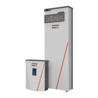
2. See Figure 4-10. Align body slots (E) with wall
bracket holes (F).
Figure 4-10. Mounting Bracket (2 of 2)
3. Fasten body to bracket with two included M4x8mm
SEMS screws in each horizontal bracket brace.
NOTE: Start screws. Do not tighten.
4. Adjust feet as necessary to ensure the feet are car-
rying the weight of the unit.
5. Check unit for plumb side to side. Adjust feet as
necessary ensure both stay in full contact with the
floor.
IMPORTANT NOTE: Do not lift the body off the
bracket by over lengthening the feet.
6. Verify there is minimum 1-3/4 in (4.45 cm) gap
between the bottom of the body and the floor.
7. Tighten machine screws to bracket and torque to
13 in-lb (1.47 Nm).
8. Verify feet have not lifted from floor.
9. Tighten feet jam nuts to lock them in place.
Installing REbus Wiring
When installing REbus wiring:
• Wiring must be installed in accordance with Article
706 in the NEC.
• Wiring must comply with local electrical codes.
• Wiring must be grounded according to local codes.
When required, grounding is the responsibility of
the installer. For proper REbus communication,
ensure the chassis is securely bonded to the
PWRcell Inverter via the grounding bar in the
PWRcell Inverter wiring compartment.
• Wiring must be protected from exposed metal
edges by using appropriate bushings, fittings, and
restraints.
• Watertight conduit fittings are required for OR
model.
• Wiring must adhere to the following specifications:
Table 4-1. Wiring Specifications
009926
A
D
C
B
009927
F
E
Specification Min Max Units
Allowable wire size 10 6 AWG
Torque 13.3 (1.5) 15.9 (1.8) lb-in (N-m)
Strip length 3/8 (10) in (mm)
Temperature rating 90 C
(000606)
Electrocution. Put the Generac PWRcell Inverter into
Safety Shutdown before installing wiring. If there are any
other batteries connected to REbus, toggle their front
Battery Disconnect switches to OFF. Failure to do so will
result in death or serious injury.
DANGER
(000607a)
Equipment damage. Never connect REbus conductors
to ground. Connecting REbus conductors to ground
could result in equipment or property damage.
CAUTION
Equipment damage. Connect only to REbus-compatible
devices to the DC bus. Never connect to any other DC
power source. Connecting to other DC power sources
could result in equipment damage.
(000598a)
CAUTION