Installing PWRcell Battery
Installation Manual for Generac PWRcell Battery 23
• When the switch is in the OPEN or OFF position
the remote shutdown will be activated. Switching to
the CLOSED or ON position deactivates the
remote shutdown.
• Installation of an external STOP switch does not
disable the Battery Disconnect Switch mounted on
the top of the battery front panel. Opening the
Battery Disconnect Switch will cause the battery
management unit (BMU) to open its contactors and
isolate the battery stack from REbus, where REbus
will still have voltage if the inverter is enabled.
Opening the battery's STOP circuit with an external
switch, however, will open the battery's contactors
and initiate a system shutdown. Once a shutdown
has been initiated, the inverter control panel must
be used to exit the shutdown and return the system
to normal functionality. The system cannot exit
shutdown mode until the remote shutdown switch
has been returned to the closed position.
• For PWRcell systems with multiple remote
shutdown STOP circuits (multiple PWRcell
devices) several configurations can be used.
1. An isolated multi-pole, single-throw NC switch
or button. Have the number of poles corre-
spond with the number of STOP device inputs
to be connected. Run a separate wire pair
from each pole of the switch to the STOP
inputs of each device. Polarity does not matter
in this case.
2. See Figure 4-14. The STOP terminals and
remote shutdown switch can be wired in one
series circuit. In this case polarity matters.
Wire the “STOP+” of first device to “STOP-” of
second device. Then wire the two remaining
“STOP” terminals to the remote shutdown
switch.
Figure 4-14. Remote Shutdown Switch Series Wiring
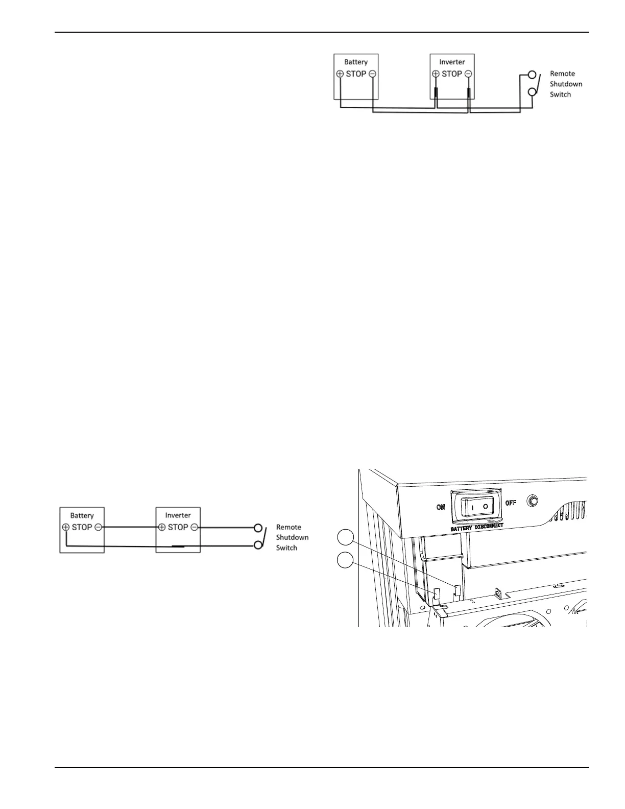
3. See Figure 4-15. The STOP terminals and
remote shutdown switch can be wired in par-
allel. In this case polarity matters. Wire the
“STOP+” of first device to “STOP+” of second
device. Wire the “STOP-” of first device to
“STOP-” of second device. From either
device, run a wire pair from the STOP termi-
nals to the remote shutdown switch.
Figure 4-15. Remote Shutdown Switch Parallel
Wiring
IMPORTANT NOTE: If polarity is wired incorrectly,
neither device will see a STOP condition and it will
not be possible to shutdown either device via the
STOP terminals until the wiring is corrected.
NOTE: Test the remote shutdown switch operation after
installation. Enable all PWRcell devices connected to the
remote shutdown switch. Initiate a remote shutdown by
opening the remote shutdown switch. Verify the system
has shutdown. After verification, disengage the remote
shutdown by closing remote shutdown switch.
NOTE: Local codes may require special labeling, indica-
tors, or other features. Requirements can vary by region,
so consult a local code enforcement officer for guidance.
Connecting Blackstart Battery
See Figure 4-16. Connect blackstart battery lead to posi-
tive battery terminal (E).
NOTE: The negative lead is already connected to termi-
nal (F).
NOTE: Do not leave blackstart battery connected if
PWRcell Battery is not connected to REbus. Blackstart
battery will enter a sleep mode and discharge to support
the unit.
Figure 4-16. Blackstart Battery Connections
012364
012365
F
012640
E