Installing PWRcell Battery
Installation Manual for Generac PWRcell Battery 29
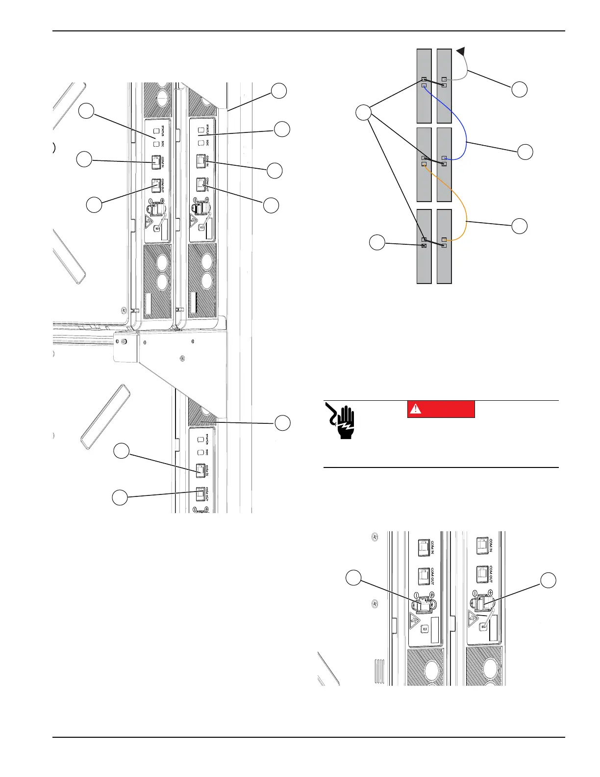
5. Connect Blue CAT 5 cable to COM OUT port (E).
6. Connect the other end of Blue CAT 5 cable to COM
IN port (G) on lower, rear battery module (F).
Figure 4-32. Module COM Cabling (1 of 2)
7. See Figure 4-33. Continue connecting the remain-
ing battery modules. While installing CAT 5 cables:
• Work from top to bottom.
• Connect battery modules sharing a shelf with a
black jumper cable (L) going from the rear battery
COM OUT port to the front battery COM IN port.
• Do not install a CAT 5 cable to the last battery
module’s COM OUT port (M).
• Remaining COM cables can be left disconnected.
• Unused CAT 5 jumpers should be kept in safe
place for future module upgrades.
Figure 4-33. Module COM Cabling (2 of 2)
Connecting Battery Power Cables
1. See Figure 4-34. Remove gray rubber cap (A)
from each module power port.
2. Plug black power cable connectors into battery
module power ports (B).
Figure 4-34. Power Cable Ports
009940
H
G
F
C
D
E
Y
Z
A
B
I Gray CAT 5
J Blue CAT 5
K Orange CAT 5
L Black CAT 5 Jumpers
009941
M
K
J
L
I
Electrocution. Never reach into port or touch
battery terminals with hands or tools. Doing so
will result in death, serious injury, equipment or
property damage.
DANGER
(000639)
009942
B
A