Installing PWRcell Battery
18 Installation Manual for Generac PWRcell Battery
Installing Foot Bracket
NOTE: A template is printed on the inside of the battery
enclosure packaging and will help locate the holes for
both wall and foot brackets.
Mount foot bracket to wall with the following procedure:
1. See Figure 4-2. Install the foot bracket bottom edge
along the bottom of the wall no higher than 5 in
(12.7 cm) above grade to keep the middle of the
Battery Disconnect Switch at a maximum height of
79 in (200.66 cm) above grade.
a. If greater height is desired, installation of an addi-
tional DC disconnect listed 30 A 600 V will be
required for the battery to meet NEC 404.8(A).
Figure 4-2. Foot Bracket Install Height
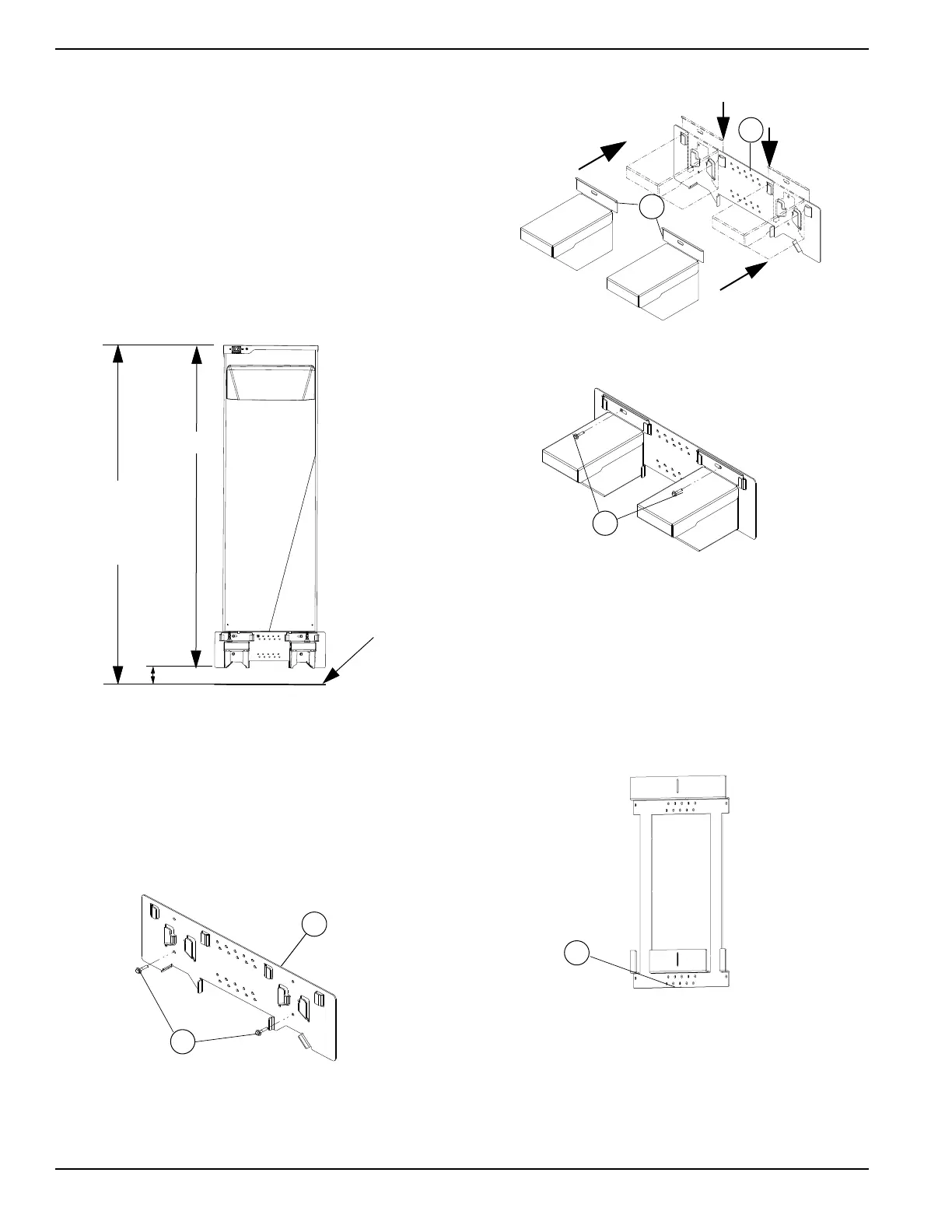
2. See Figure 4-3. Locate structural members to
mount foot bracket (A). If structural members are
greater than 16 in (40.64 cm) apart, install cross
brace to ensure mounting to a solid structure.
3. See Figure 4-3. Install foot bracket (A) using lower
holes with fasteners and washers (B) making sure
bracket remains plumb and level.
NOTE: Do not install the top fasteners at this stage. This
will inhibit installation of the stands.
Figure 4-3. Install Foot Backet
4. See Figure 4-4. Slide foot stands (C) onto foot
bracket (A) making sure underside of pockets clear
bottom bracket before engagement. Proper installa-
tion is achieved by lining up the top edge of foot
bracket to the bottom edge of the stands.
Figure 4-4. Insert Stands Onto Foot Bracket
5. See Figure 4-5. Use flat washers and fasteners (D)
to secure top of foot bracket and stands.
Figure 4-5. Install Top Fasteners Through Stands and
Foot Bracket
Installing Wall Bracket
NOTE: Included with PWRcell Battery.
• See Figure 4-6. Bottom edge (A) is 29-5/8 in (752
mm) off the floor for installations that are not
elevated. See the following procedure for elevated
installation or use the to-scale template printed on
the inside of the battery enclosure packaging.
Figure 4-6. Wall Bracket
Mount Wall Bracket to wall with the following procedure:
1. See Figure 4-7. Project a vertical line up from the
top mounting fastener in the foot bracket (B).
2. Place a mark on the projected line 30 11/16 in
(779.2 mm) above the top mounting fastener of the
foot bracket (B).
013072
Grade
5 in Max
80 in
(79 in
to middle of
switch)
75 in
011153
A
B
011155
C
A
011156
D
009920
A