Installing PWRcell Battery
28 Installation Manual for Generac PWRcell Battery
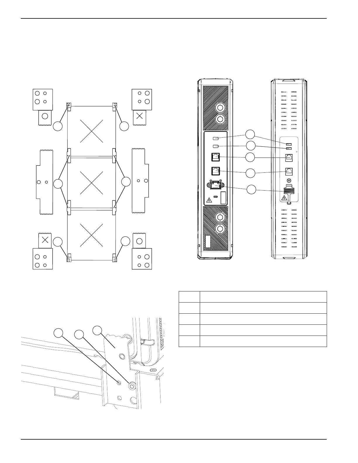
See Figure 4-29. Note that there are three types of
retainer clips: double retention clips (U), single retention
clips marked O (T) and single retention clips marked X
(S).
• Install single retention clips (T) (S) at the top and
bottom of the stack.
• Install double retention clips (U) between rows of
modules.
Figure 4-29. Installing Retention Clips (2 of 3)
To install retention clips:
1. See Figure 4-30. Align holes in retention clip (V)
with stud (W) and mounting hole (X).
Figure 4-30. Retention Clips (3 of 3)
2. Apply gentle pressure to ensure all grounding tabs
and clips make firm contact with case.
3. Secure retention clip to bracket with a M4X8 mm
screw and torque to 13 in-lb (1.47 Nm).
Connecting COM Cables
See Figure 4-31 for a description of the module connec-
tions and indicator lights.
Figure 4-31. DCB (left) and EX Module (right)
Connections
1. See Figure 4-32. Locate multicolored CAT 5
cables attached to battery power cable harness on
body (Y) and top, rear battery module (Z).
2. Connect Gray CAT 5 cable to battery module COM
IN (A)
3. Connect Black CAT 5 jumper to battery module
COM OUT (B).
NOTE: Black CAT 5 jumper is found in hardware kit.
4. Connect the other end of Black CAT 5 jumper to
COM IN port (D) on front battery module (C).
009938
T
S
U
U
ST
009939
X
W
V
A Status LED
B SoC LED
C CommIn Port
D CommOut Port
E Battery Connection Power Port
SOC
STATUS
COM IN
COM OUT
Status
SOC
CommIn
CommOut
-
+
WARNING CANCER AND REPRODUCTIVE HARM - www.P65Warnings.ca.gov.
012286
A
B
C
D
E