Model 4802A
Quick-Start Guide
ix
The table below refers to the proper open and closed A1 alarm relay contacts while the
unit is on power:
User Selected
Relay State
Normally
Open
Normally
Closed
Normally
Energized
A1-C1 & A1-1,
A1-C2 & A1-4
A1-C1 & A1-2,
A1-C2 & A1-3
Normally
De-Energized
A1-C1 & A1-2,
A1-C2 & A1-3
A1-C1 & A1-1,
A1-C2 & A1-4
Figure 6b – A1 Alarm Relay Contacts
1.5.3 Fault Alarm
The terminal designations for the Fault outputs are:
Label Term Description
F-C 16z Relay Common
F-1 18z Relay Contact (NO)
F-2 20z Relay Contact (NC)
F-OC 22z Open Collector (OC)
FUA 32d Open Collector (OC)
Figure 7 – Rear Terminal Designations for Fault Outputs
The Fault outputs are SPDT relays, 1 open collector output (F-OC) that follows the
logic of the relays and 1 open collector output (FUA) dedicated to new fault indications.
NOTE - If the Backward Compatible configuration is ordered, the FUA will not be
present (pin 32d will be for +B).
The Fault outputs are always normally energized when power is applied to the module.
The contact ratings for the A2 & A1 alarm and Fault relays are 4A @ 250 Vac, 3A @ 30
Vdc, Resistive, maximum.
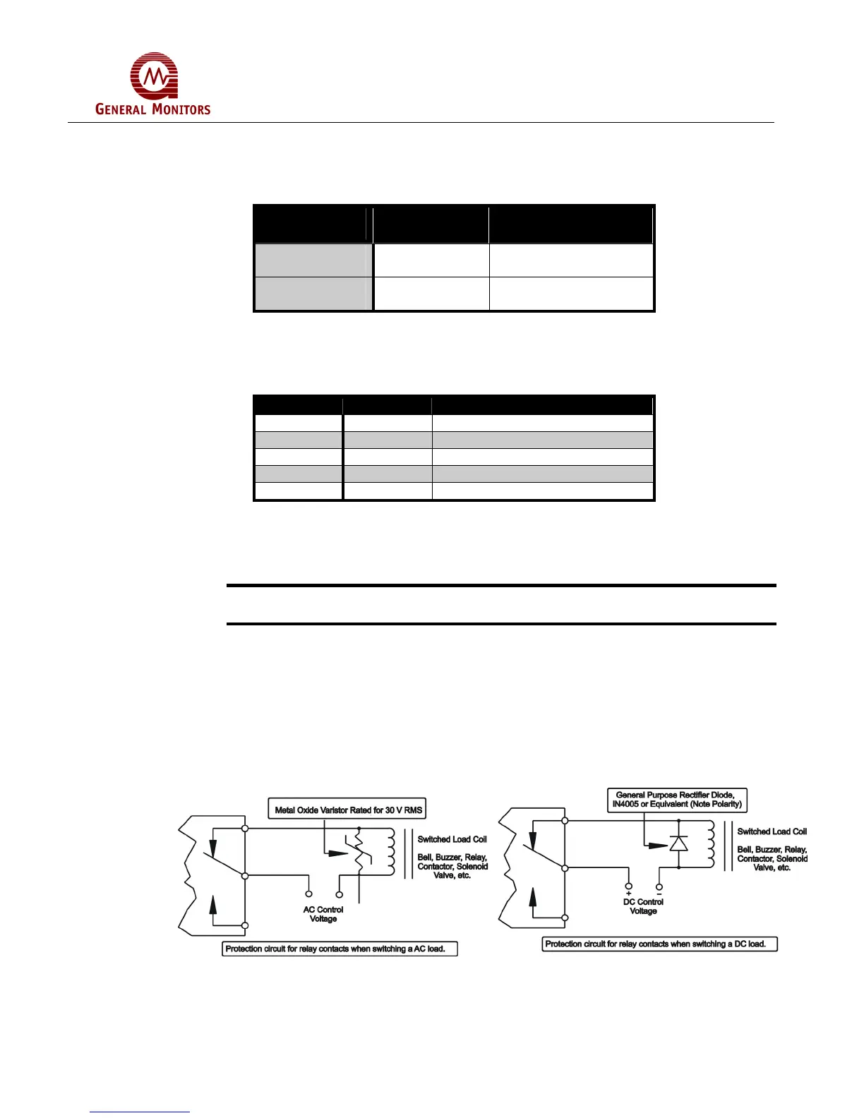
Inductive loads (bells, buzzers, relays, etc.) on dry relay contacts must be clamped
down. Unclamped inductive loads can generate voltage spikes in excess of 1000 volts.
Spikes of this magnitude may cause false alarms and contact damage. Figure 8 shows
recommended relay protection circuits for AC and DC loads, respectively.
Figure 8 – Relay Protection Circuits for AC and DC Loads
 Loading...