Model 4802A
Quick-Start Guide
viii
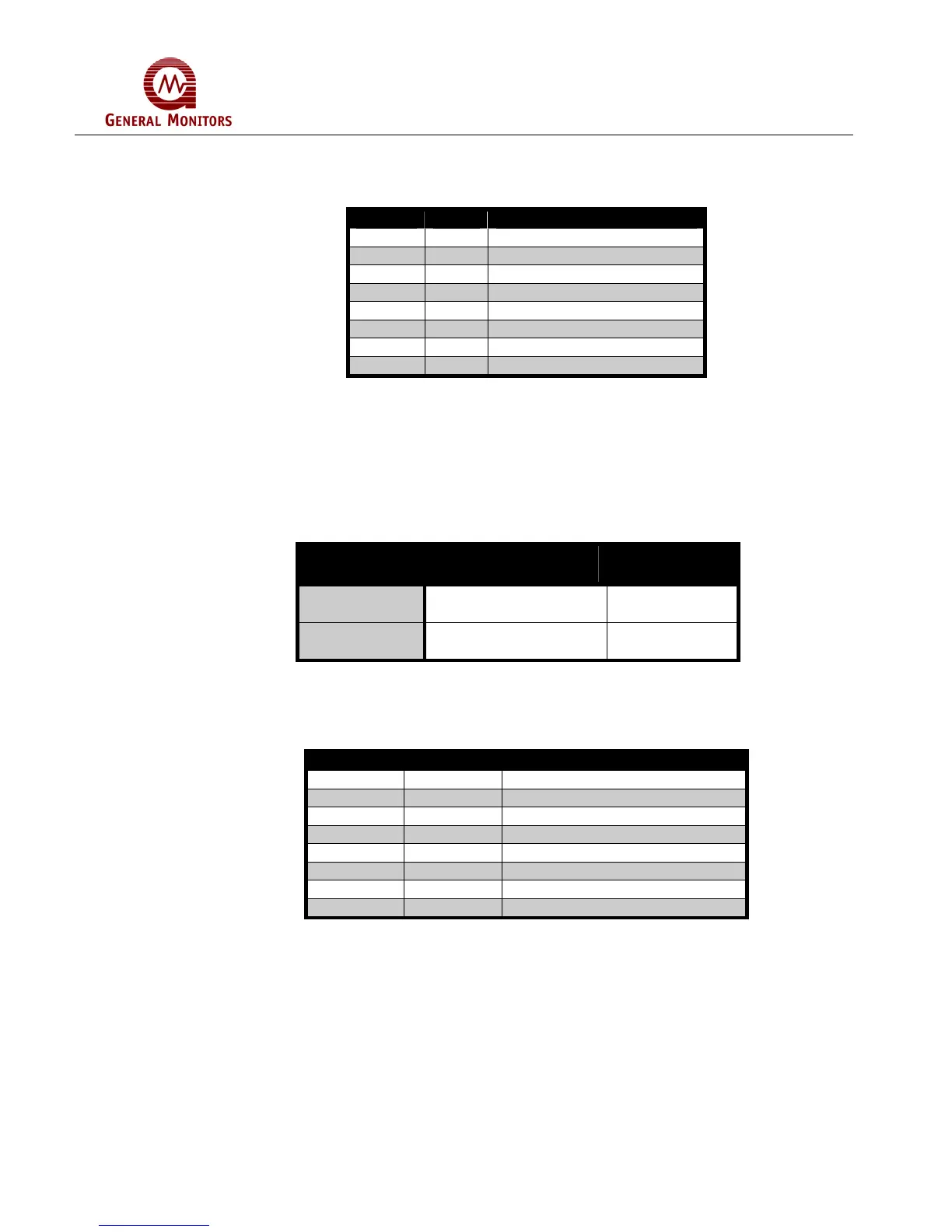
1.5.1 A2 Alarm
The terminal designations for the A2 alarm outputs are:
LABEL TERM DESCRIPTION
A2-C1 2d Relay Common (1 & 2)
A2-1 4d Relay Contact
A2-2 6d Relay Contact
A2-3 8d Relay Contact
A2-4 10d Relay Contact
A2-C2 12d Relay Common (3 & 4)
A2-OC 14d Open Collector (OC)
LA2 24z OC Logic for A2 LED
Figure 4 – A2 Alarm Outputs
The A2 alarm outputs are DPDT relays, 1 open collector output (A2-OC) that follows
the logic of the relays and 1 open collector output (LA2) that follows the blinking pattern
of the front panel LED. The A2-C1 designation is common for A2-1 & A2-2. The A2-C2
designation is common for A2-3 & A2-4. The normally open (NO) and normally closed
(NC) contacts depend on a user selectable option (see Chapter 5). The table below
refers to the proper open and closed A2 alarm relay contacts while the unit is on
power:
Figure 5 – A2 Alarm Relay Contacts
1.5.2 A1 Alarm
The terminal designations for the A1 Alarm outputs are:
Label Term Description
A1-C1 2z Relay Common (1 & 2)
A1-1 4z Relay Contact
A1-2 6z Relay Contact
A1-3 8z Relay Contact
A1-4 10z Relay Contact
A1-C2 12z Relay Common (3 & 4)
A1-OC 14z Open Collector (OC)
LA1 24d OC Logic for A1 LED
Figure 6a – A1 Alarm Outputs
The A1 Alarm outputs are DPDT relays, 1 open collector output (A1-OC) that follows
the logic of the relays and 1 open collector output (LA1) that follows the blinking pattern
of the front panel LED. The A1-C1 designation is common for A1-1 & A1-2. The A1-C2
designation is common for A1-3 & A1-4. The normally open (NO) and normally closed
(NC) contacts depend on a user selectable option (see Chapter 5).
User Selected
Relay State
Normally
Open
Normally
Closed
Normally
Energized
A2-C1 & A2-1,
A2-C2 & A2-4
A2-C1 & A2-2,
A2-C2 & A2-3
Normally
De-Energized
A2-C1 & A2-2,
A2-C2 & A2-3
A2-C1 & A2-1,
A2-C2 & A2-4