Model 4802A
Quick-Start Guide
xii
Figure 14 is a block diagram that shows the switch connections for the Card Test
feature.
Figure 14 – Switch Connections for Card Test
The Card Test Input is provided so that the user can access the Card Test feature
remotely. One end of a normally open SPST switch is connected to this termination.
The other end is connected to system common. To activate the feature, simply press
and hold the switch for as long as the test time is to be run.
1.5.7 Analog Output Signal
The terminal designations for the Analog Output Signal are:
Label Term Description
AO+ 20d Analog Signal (plus)
AO- 22d Analog Signal (minus)
Figure 15 – Terminal Designations for Analog Output
NOTE - If the Analog Signal is not used, a jumper must be placed between 20d & 22d.
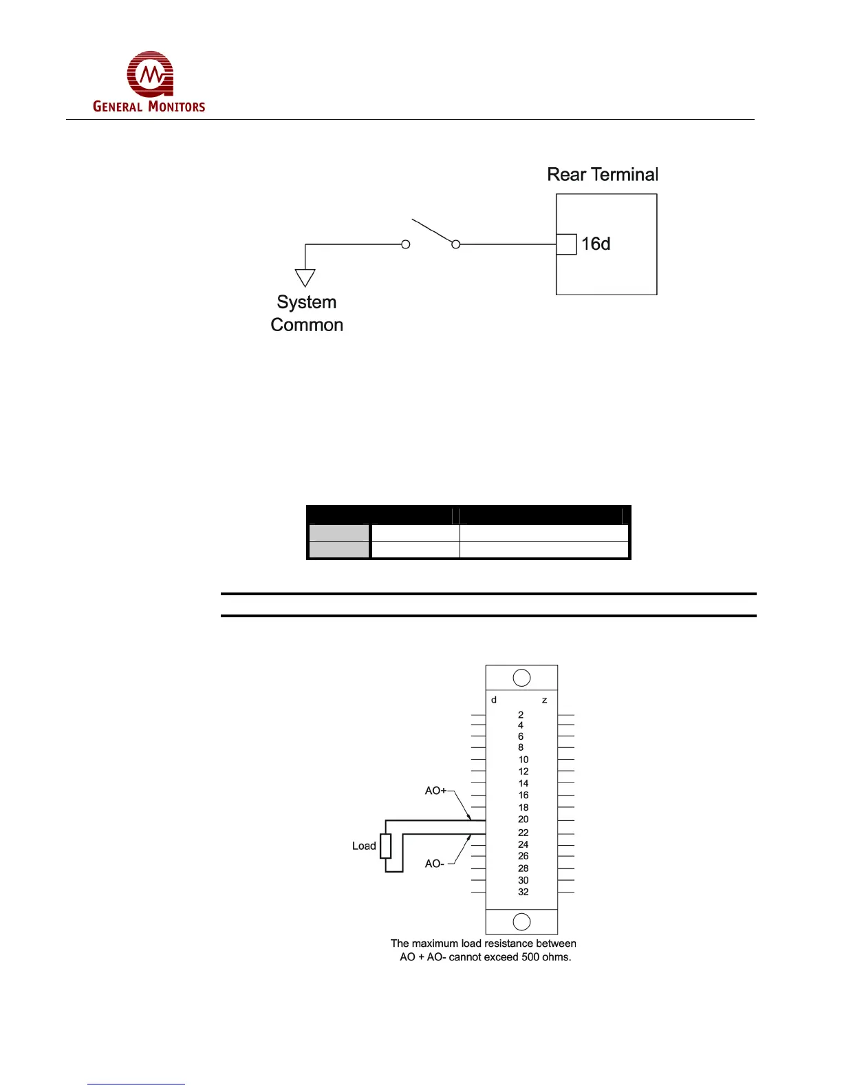
Figure 16 is a diagram of the Analog Signal connections.
Figure 16 – Analog Signal Connections