12 13
2. NMEA 2000 network connection
white wire NET H pin 3
blue wire NET L pin 4
black wire NET C pin 6
red wire NET S pin 7
SHIELD pin 5
WARNING: To ensure a safe installation, the shields of connecting cables should be
grounded, i.e., connected to the boat’s ground.
NOTE: Network connection requires the use of suitable connectors and an auxiliary
power supply, as established by the NMEA 2000 standard. Technical features and
connection modes are reported in the technical document issued by the National
Marine Electronic Association (for further information, go to the http://www.nmea.org
web site). Only skilled personnel should be charged with making the connection.
CONNECTIONS
Power supply and data connector (9 pins)
1. Power supply
red wire + VDC pin 1
black wire GND pin 2
2. NMEA 0183 data input
brown wire GPS IN + pin 3
yellow wire GPS IN - pin 4
3. NMEA 0183 data output
violet wire DATA OUT + pin 5
white wire DATA OUT - pin 6
4. Auxiliary output voltage (Vaux)
blue wire Vaux+, 250mA * pin 7
green wire GND pin 8
SHIELD pin 9
* Vaux voltage is the same as the plotter’s input voltage.
If sent by the position sensor, the following NMEA messages
are transmitted to external devices (e.g., autopilot):
APB - XTE - RMB - BWC - GLL - VTG
The GEONAV will add the following messages (if received
from the position sensor):
GGA - RMC - ZDA
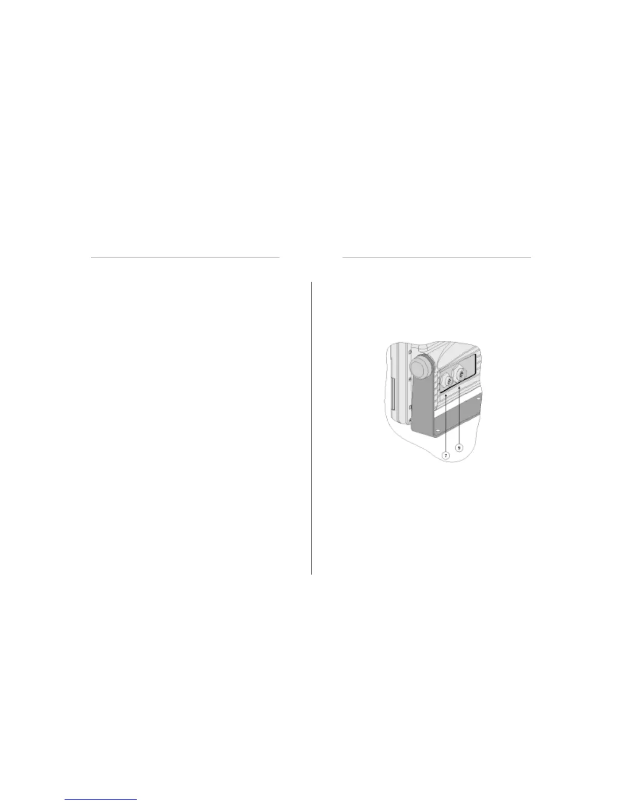
Auxiliary connector (7 pins)
Allows connecting the GEONAV to an auxiliary instrument
equipped with an NMEA 0183 interface (e.g., echosounder
and mast head transducer), as well as to the NMEA 2000 net-
work.
1. NMEA 0183 auxiliary data input
brown wire DATA IN + pin 1
yellow wire DATA IN - pin 2
Connections