Comander Perimeter Security System
Engineering and Installation Manual
Page 12 of 72
1.8 Comander System Architecture Examples
1.8.1 Single Comander System
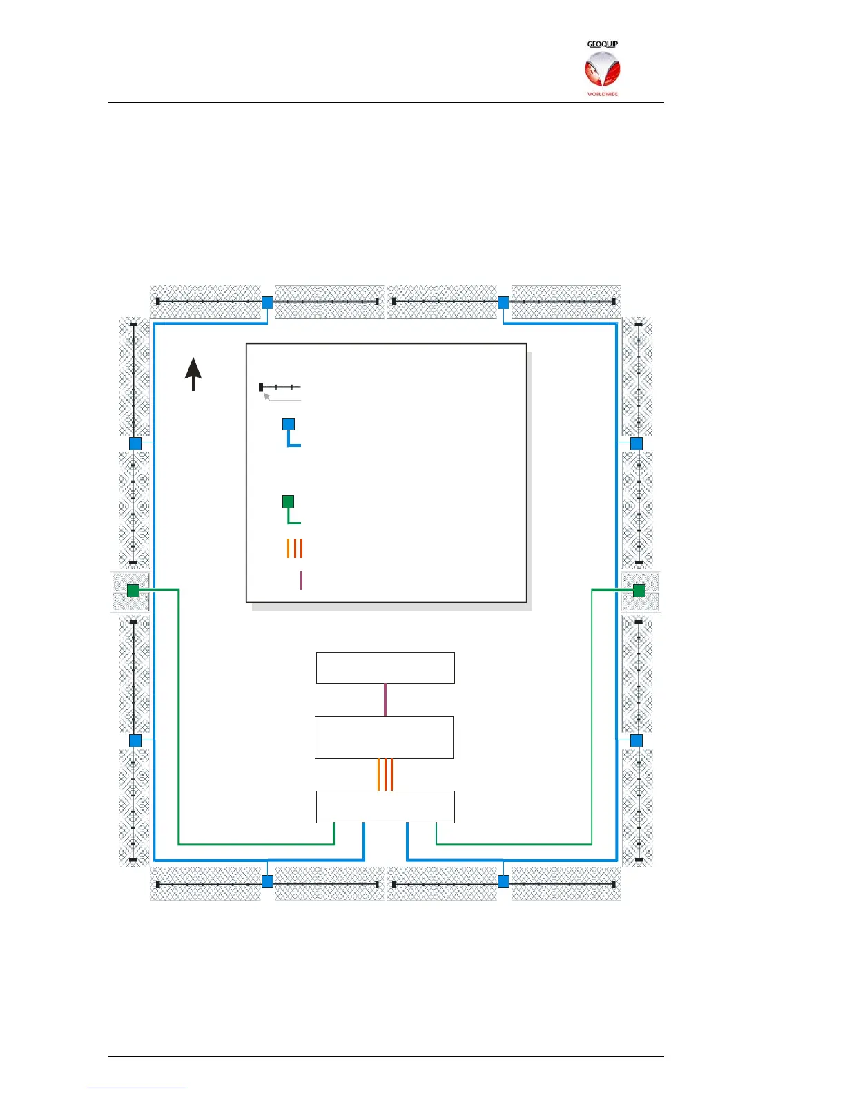
In its simplest implementation, a Comander unit can be used as a standalone intruder
detection and alarm system. In this example, a square perimeter with two gates is
divided into 16 zones, with the fence in each zone protected by an Interceptor cable. It
is not a very realistic example, but serves as a useful illustration of the basic principles
of Comander-based detection systems.
N
Marshalling Box
1D Relay Rack
Comander Rack
IP 10.2.3.100 / 24
Fence-mounted Interceptor Cable
End-of-Line Termination Box
Dual Junction Box
Gate Switch Monitored Contacts
Feeder Cable - 1 pair per Contact
Interceptor and Contact Connections
Serial RS232 Connection
Feeder Cable - 5 pairs:
2 x Interceptor Cable
2 x Termination Box Tamper Switch
1 x Junction Box Tamper Switch
KEY
1.8.1.1 Interceptor and Contact Inputs
The Interceptor cables are connected on the fence to Junction Boxes, and the
Interceptor signals are carried by Feeder Cables back to the Comander Marshalling
Box, which is located along with the Rack in a control room. Each Junction Box
contains a microswitch which is connected separately as a Monitored Contact circuit,
ensuring intrusions into the Junction Box can be detected as a Tamper condition.
Note that each Interceptor cable must be terminated in an End-of-Line Termination