Comander Perimeter Security System
Engineering and Installation Manual
Page 49 of 72
In this configuration the sensor is able to detect vibrations in the upper part of the fence
fabric which would not affect the lower part of the cable sufficiently to cause an alarm.
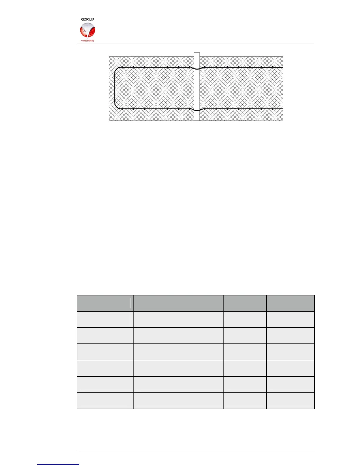
5.2.4 Dual Fabrics
When the fence is of two distinct fabrics, (for example a chain-link fence with razor-wire
topping), two separate runs of sensor cable may be deployed to give the best possible
protection. One run is situated along the lower part of the fence, firmly attached to the
fabric, while the other is attached to the topping - each of the two sensors is then
connected to a separate electronic analyser. In this configuration the user is able to
adjust the Interceptor analyser settings for the two sensors separately, to cater for the
different disturbances and vibrations of the different fabrics. See section 2.5.5 above
for information about Interceptor analyser configuration.
5.2.5 Fence Types
The extent of the sensor’s detection range - its ability to detect vibrations in the fence
some distance away - depends on the rigidity of the fence fabric. Thus the height of
fence that can be protected by a single run of the sensor varies according to the type of
fabric.
Any fence higher than 2.4m will need a double run of cable, but this will also be needed
on some lower fences. The two most common types of fencing used in perimeter
protection are chain-link and weld-mesh, and the table below shows whether the
sensor should be used in single or double runs for fences up to 2.4m high.
Fence Type Gauge Single Run Double Run
Chain Link
Light - 2mm Y
Medium - 3mm Y
Heavy - 4mm+ Y
Weld Mesh
50mm x 50mm x 2mm Y
75mm x 75mm x 3mm Y
Grille Type Y
5.2.6 Handling Precautions
In order to maintain the high-quality performance of the sensor cable, it must be
correctly handled and installed. It is important that the conductors remain able to move
freely within their Lubritube sleeves, so the cable should not be subjected to excessive