Comander Perimeter Security System
Engineering and Installation Manual
Page 41 of 72
3 Diagnostics and Troubleshooting
The Comander Rack and Marshalling Box have a number of LEDs which indicate
status and diagnostics. Each Rack can also output a stream of "Debug" data to assist
with diagnosis of complicated problems.
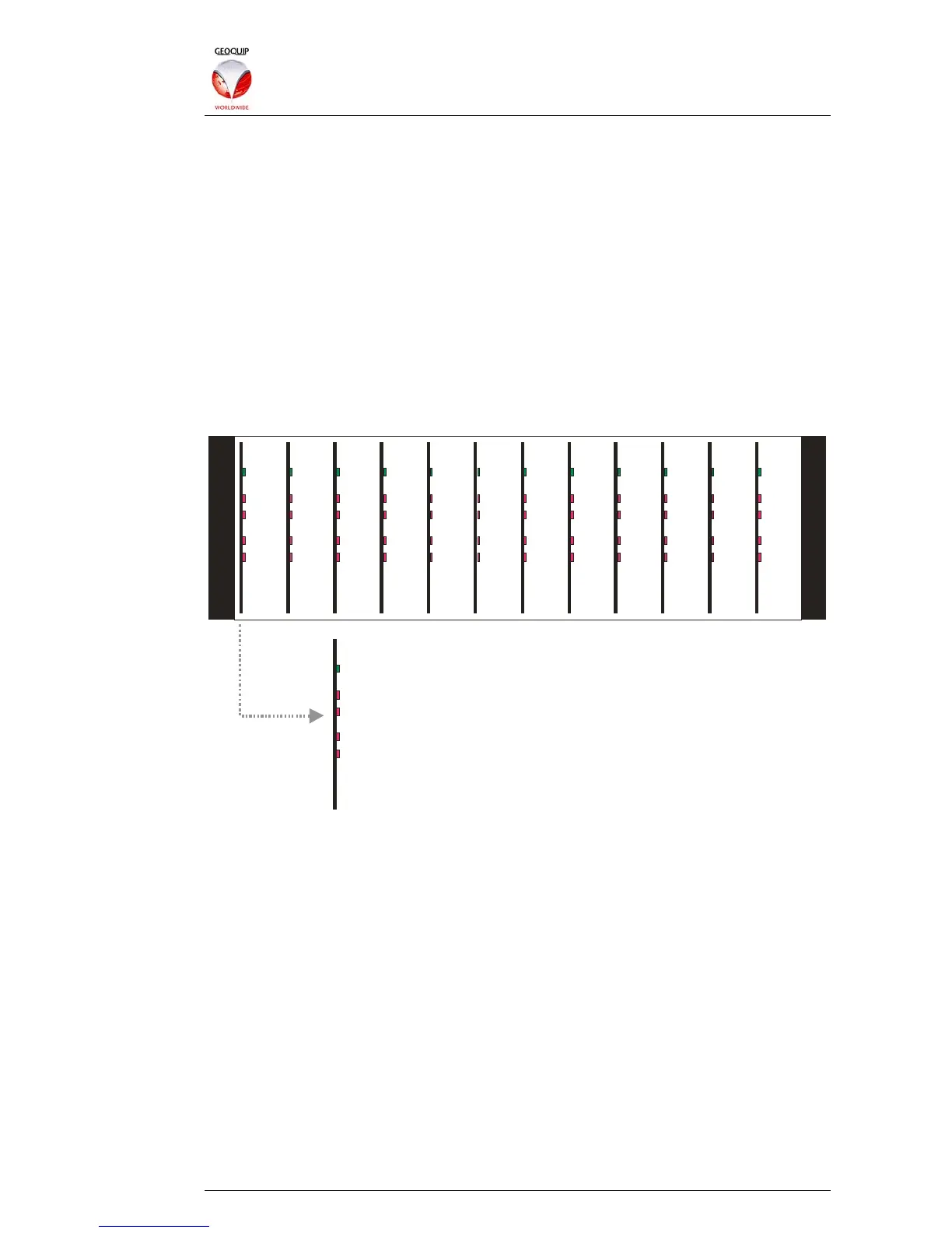
3.1.1 Interceptor Analyser Status LEDs
To see the Interceptor Status LEDs, you must remove the front panel of the Comander
unit.
Once you have removed the front panel, you will see the Interceptor Analyser cards –
these are plug-in cards, with each card analysing two Interceptor circuits. A full
Comander Rack has 12 cards, supporting 24 Interceptor circuits. Each card has a
green LED indicating that it is working, and four red LEDs indicating Alarm and Tamper
conditions for its two Interceptor circuits:
1-2
Green = Card Status OK
Red : Flashing=Channe l 1 PreAlarm, Continuous=Channel 1 Alarm
Red : Flashing=Channe l 2 PreAlarm, Continuous=Channel 2 Alarm
Red: Channel 2 Tamper
Red: Channel 1 Tamper
3- 4 5- 6
7-8
9-10 11-12 13-14 15-16 17-1
19-20 21-22 23-24
3.1.2 Rack Status and Diagnostic LEDs
To access the LEDs inside the Rack unit, remove the lid from the top of the unit, and
look at it from the rear, with the various inputs and outputs facing you. This should
provide a good view of the main Comander PCB.
There are two blocks of status LEDS – a block of 24 blue status LEDs, located at the
top of this board, right of centre, and a block of 8 red COM port LEDs, located left of
centre.