Comander Perimeter Security System
Engineering and Installation Manual
Page 15 of 72
the Comander system – for the CCTV system, the Comanders are acting purely as
Ethernet switches, and the fibre connections purely as a transport.
1.8.2.2 SMS Collator
This scenario is a good example of where the Comander's SMS Collator functionality is
useful. The SMS Collator would be enabled on the Control Room Comander Rack,
and this Rack would collate all the circuit information from the other Comanders in the
Ring, and present it to the SMS as a single contiguous list of circuits. See section 1.5.2
and 2.5.7 for more information about the SMS Collator.
1.8.2.3 Network Topology
Because this scenario uses a group of Comanders connected as a Ring, the Network
Topology feature in the Control Room Comander Rack can be used to monitor
connectivity and detect damage or sabotage to the perimeter network connections in
real time. The Network Topology system has a dedicated page in the Comander
Configurator – note that it should only be enabled on ONE Comander in a system.
In this case, the Network Topology RSTP option is enabled on the Comander located
in the Control Room, IP 10.2.3.100, by ticking the RSTP Enable checkbox on the
Network Topology page of that Rack's Configurator. The Configurator page has a
second option for enabling a UDP broadcast of any errors – when properly interpreted
by the SMS software, this information allows the operator to locate the break in the
Ring.
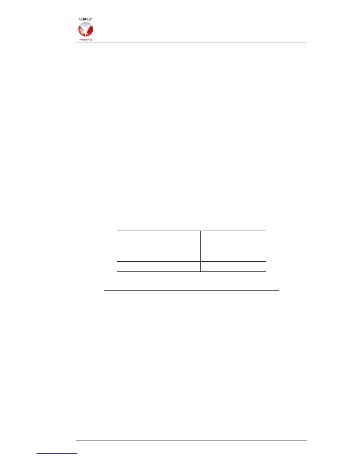
The Ring information would be entered into the Comander's Network Topology
Configurator as follows:
Network IP Entry 01 10.2.3.101
Network IP Entry 02 10.2.3.102
Network IP Entry 03 10.2.3.103
Network IP Entry 04 10.2.3.104
Note that the IP address of the local Comander Rack is NOT
included in its own Network Topology list.
The list does not include any IP addresses on the CCTV subnet. In this example, no
useful information could be obtained by including these addresses, because they are
connected as spurs on the Comander ring. In some specific situations, IP addresses
from other subnets or spur connections can be usefully included in the Network
Topology list – an example of such a scenario is given in section 4 of this manual – but
in this simple example, only the Comander IPs can provide useful information to the
Topology system.