Comander Perimeter Security System
Engineering and Installation Manual
Page 66 of 72
6 Connecting Sensors to the Marshalling Box
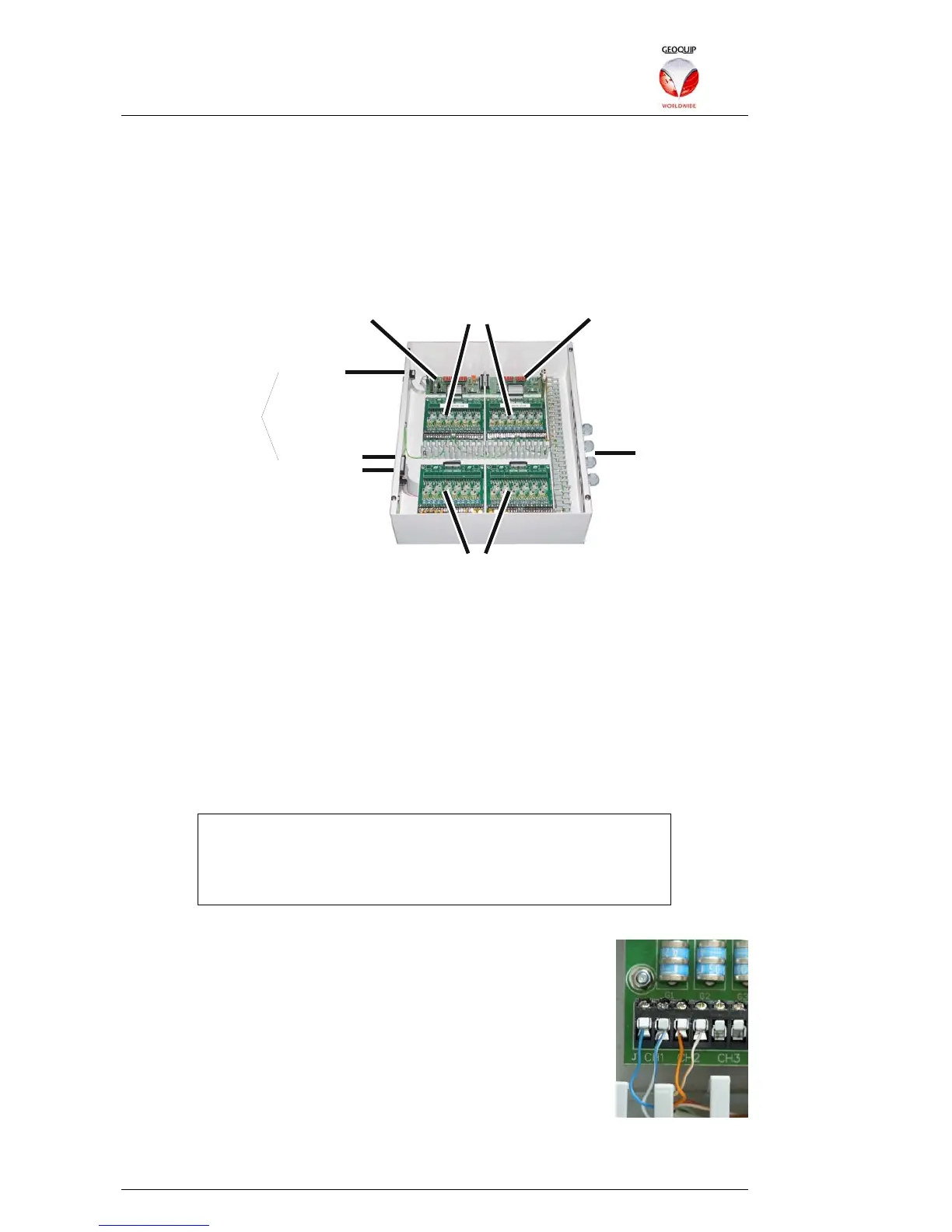
A Comander Marshalling Box acts as a hardware hub for any Interceptor cables or
Monitored Contacts connected to the Comander Rack. Cables are brought into the
Marshalling Box and terminated on the lightning protection boards inside it, and the
signals from these cables are routed onwards to the Comander Rack via multiway
cables (for the Interceptor signals) and a custom multiplexed serial data link (for the
Monitored Contacts). See section 1.3.1 above for information about connecting the
Marshalling Box to the Comander Rack.
Interceptor Protection Boards
Contacts Protection BoardsContacts Master Board Contacts Slave Boar
Contacts
Inte rceptors
Rack Connections
Incoming
Feeder Cables
Because different Comander systems might require different numbers of Contacts and
Interceptors, the Marshalling Box design is flexible – if fewer Interceptor cables are
required, extra Monitored Contacts boards can be fitted instead, providing up to 48
Contacts in one Marshalling box. If required, an additional slave Marshalling box with
another 48 Contact inputs can be added, providing up to 96 Contacts in total.
If more than one Marshalling box is used, the Contacts from the Slave box must be
connected to the Contacts boards in the main Marshalling box using a 26-way ribbon
cable – see section 6.2.1 below.
Each incoming Contact or Interceptor connection cable arrives in the Marshalling box
via a weatherproof gland, and is connected to a pair of terminals on one of the
appropriate lightning protection boards.
The Comander Rack and the Marshalling Box are rated for use in
Industrial temperature ranges, but their enclosures are NOT IP65-
rated, and cannot be fence-mounted. If the units are installed on
a perimeter rather than in a control room, they must be housed in
a weatherproof enclosure.
6.1 Connecting Interceptors
Each Interceptor cable is terminated in a junction box on the fence,
and its signal is brought to the Marshalling Box using a Feeder
Cable (see section 5.5 above). Each Feeder Cable has one or
more twisted pairs of insulated conductors, and an earth shield.
The earth shield must be connected to an earth terminal inside the
Marshalling Box, and the insulated conductors must be connected
to the two screw-terminals provided for the Interceptor channel on
the lightning protector circuit boards.
The Interceptor cable signals are fed from the protection boards directly into the
multiway cables which connect the Marshalling Box to the Comander Rack.