Comander Perimeter Security System
Engineering and Installation Manual
Page 67 of 72
6.2 Connecting Monitored Contacts
Like the Interceptor Feeder cables, Monitored Contact signals are brought in to the
Marshalling box using insulated twisted-pair cables. Contact inputs should be
terminated on the lightning protection boards in the same way, but the lightning
protection boards used for Contacts are connected to "Collator" boards, using 26-way
ribbon cables. The Collator aggregates all the Monitored Contact inputs into a serial
data stream, which is then sent to the Comander Rack using the dedicated Contacts
input on the rear panel (see section 1.3.1.2 above).
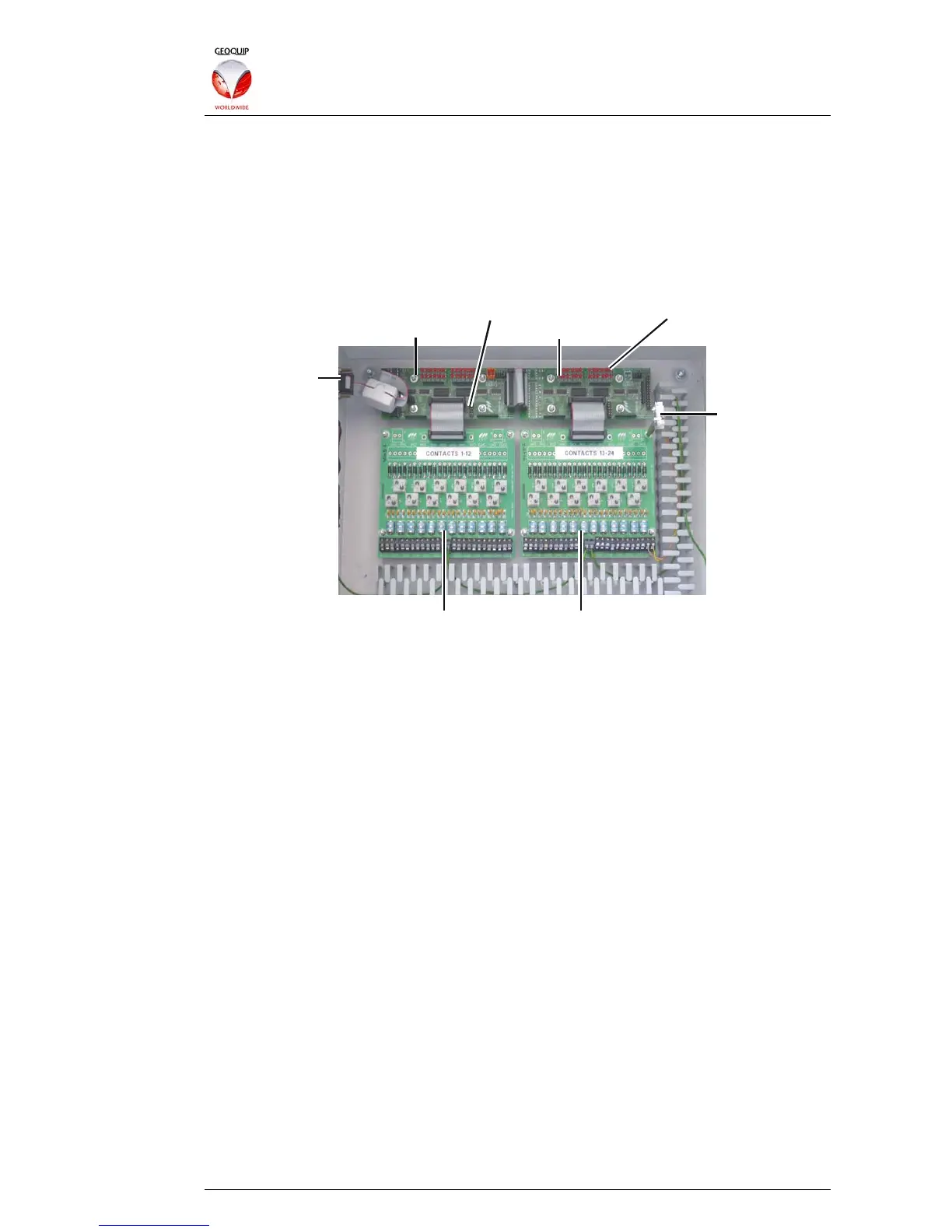
Collator Master
Collator Configuration Links Circuit Status LEDs
Output
to Rack
Lightning Protection Boards
Collator Slave
Lid
Tamper
Switch
Typically, a Marshalling Box is fitted with a lid-tamper microswitch, which is connected
to a Monitored Contact input inside the box, and configured as a Tamper-Only circuit –
in this case it is connected to input 24 (bottom right).
(Note that some installers use input 1 (bottom left) as the Tamper-Only circuit for the
Lid Tamper Switch, rather than input 24. This is not shown in the diagram.)
6.2.1 Contact Collator Boards
Each Marshalling Box has one or more Collator boards, each of which can manage up
to 24 Contacts. Each Collator board has two 26-way headers, for connecting two
lightning protection boards – in the illustration above, only one header is used on each
Collator, so each Collator has 12 inputs.
Collator boards are available in two variants – Master (which includes the
microprocessor which multiplexes and streams the Contact data) and Slave (which is
purely passive and does not have the microprocessor fitted). Each Master collator
board can support up to three Slave boards - so a single Comander Rack can support
up to 96 Monitored Contact inputs, depending on the configuration of Marshalling Box
hardware.
The illustration above shows the standard Marshalling Box configuration of 24
Monitored Contacts, using two lightning protection boards, with one Master Collator
and one Slave. If more Contacts are required for a particular Rack, different
Marshalling Box configurations or additional Marshalling Boxes can be used to house
the extra lightning protection and slave collator boards. The Collator Configuration
links (see illustration above) are used to configure the Master Collator for different
arrangements of Slave boards.
For specific information on Marshalling Box variants and how to configure different
arrangements of Contact boards, please consult Geoquip Technical Support.